This thread has been locked.

If you have a related question, please click the "Ask a related question" button in the top right corner. The newly created question will be automatically linked to this question.

UCC256403: changing regulation behavior

Part Number: UCC256403
Other Parts Discussed in Thread: TL431

I'm evaluating the possibility to use the UCC256403 in my current design.
Because of mechanical restrictions I can't implement a direct feedback
from secondary side using the common TL431/optocoupler combination.
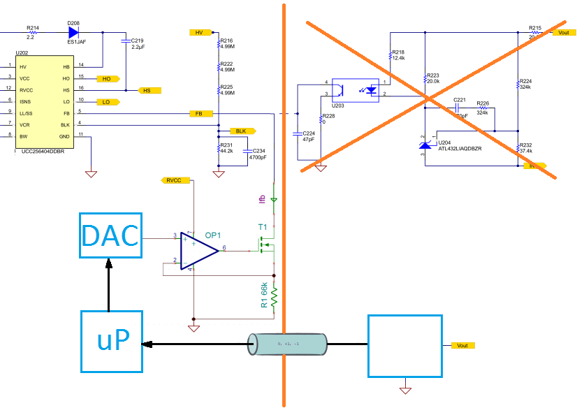
Secondary side's output will be used to control my plant (maybe controlled system is a better translation for "Regelstrecke").
I want to convert plant's output to a voltage, which I feed via
an OP-AMP and the TL431/optocoupler combination back to the UCC256403.

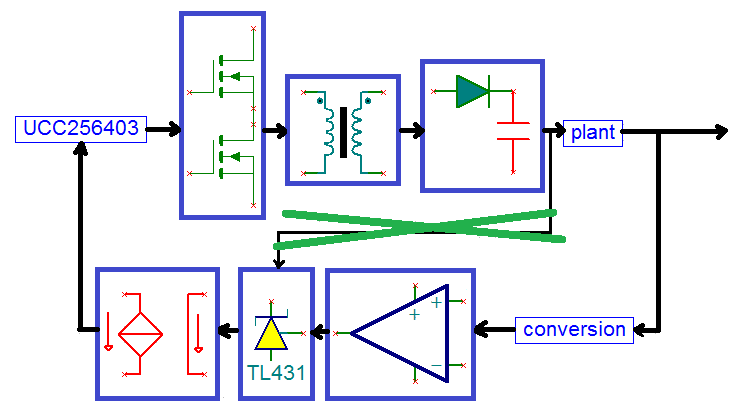
I've emulated that approach with an EVM-020 board.


The conversion block I've relised with a simple voltage divider 12V => 9.75V
and by removing R56 I instructed the EVM-020 circuit to regulate to that 9,75V.

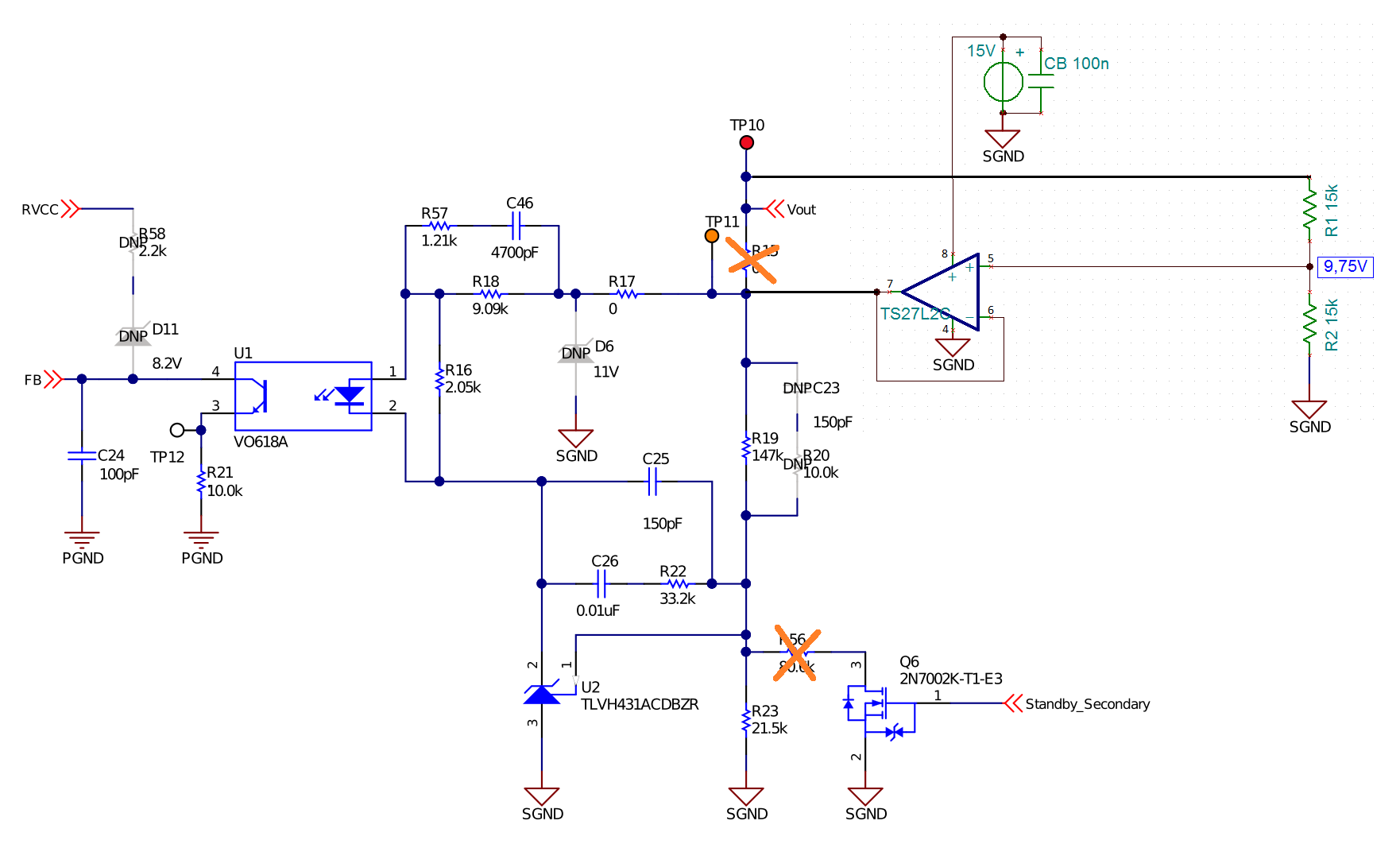
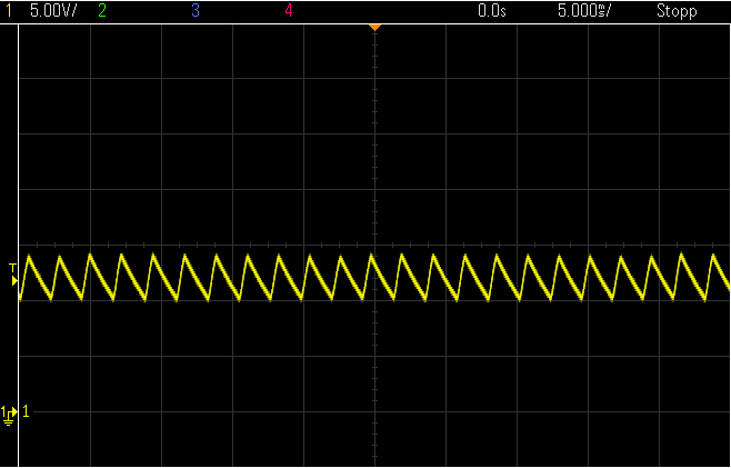
It seems, the approach works, when I test it with load steps,
even though the regulation doesn't work very "fine".

I think, the poor regulation ist a result of an low pass
I've added into the feedback pass by using an OP-AMP (the only one
fast available) with a small gain bandwidth product.

Because I suppose, my plant has an even lower cutoff frequency,
I've lowered the cutoff frequency of the OP-AMP even more.

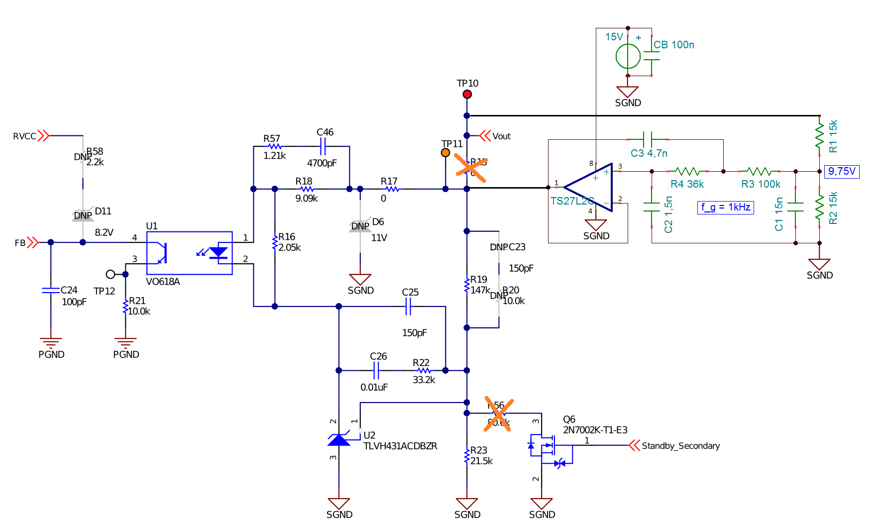
As feared, the regulation will fail to work then!


Is there a chance, to manipulate UCC256403's "aggressive" regulation behavior,
it will worked also correctly with a "low pass filter" in the control loop - making it "slower"?
Which components I have to change then?

  • Hello,

    The first feedback circuit  the TL431 is trying to regulate the output of the TS27L26 at 9.72V.  You have the non inverting pin of the TS27L26 set to 9.75V.  I believe this might be causing your load regulation issue. These two should fight each other

    The second feedback that you have added has more gain and is even more unstable.  So I don't recommend using that feedback scheme either.

    I would recommend just using the TL431 feedback and just adjusting R23 to obtain 19.5 V. 

    If you are just trying to have an open loop circuit.  You could remove U2, C26 and C25 and put a potentiometer from U1 pin 2 to ground.  Adjusting the current will adjust the switching frequency.

    Regards,


  • Hello,

    I haven't two feedback paths, because aside R56 I have also removed R15. I can't use this feedback,

    because secondary side will rotate against primary side using a rotary transformer in my end application.

    I will get a feedback from the "end output" of the controlled system in my end application, which I will convert

    to a voltage around 9,72V (the EVM-020 documentation says 9,75V) and feed to the TL431/optocoupler combination

    by an OP-AMP.

    I emulate that on my bread board by dividing the 12V by a voltage divider (R1 = 15k, R2 = 62k - in my images I've R2 = 15k, that's wrong) .

    The EVM-020 will then regulate Vout to a level, that OP-AMP's non inverting input will see 9,72V.

    That works with the in first case, but not in second case, when I lower the cutoff frequency of my OP-AMP circuit.

    And question was - is there a possibility,  to change UCC256403's regulation behavior, when I have a low pass in my control loop.

  • Your last remark is interesting - maybe my approach using a Microprocessor controlled voltage to current converter

    https://e2e.ti.com/support/power-management/f/196/t/883334 ) will work - when I can lowering the

    switching frequency towards the resonant frequency by lowering I_FB and higher it by highering  I_FB,

    I should be able to control my end output. My voltage to current converter should be able to convert 0..3.3V to 0..165uA then!?

  • Hello Even though R15 is removed the voltage divider fed by R19 and R23 is going to try to control the output of your amplifier to 1.24V.  This is going to going to fight your feedback scheme and will cause you issues.

  • Hello,

    I think your last suggestion is a better approach and should be more stable than what you were doing.

    Regards,