This thread has been locked.

If you have a related question, please click the "Ask a related question" button in the top right corner. The newly created question will be automatically linked to this question.

TLV757P: Batch performance issue

Part Number: TLV757P

Hi,

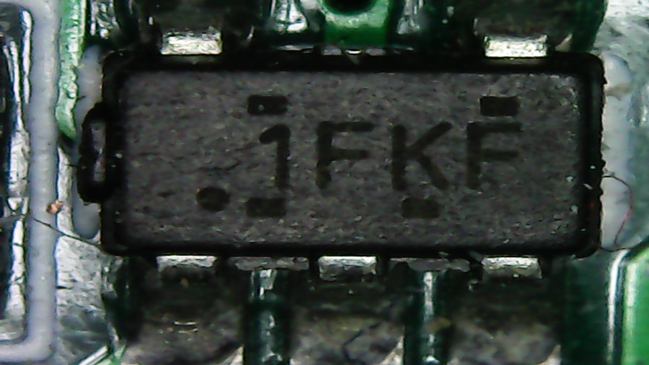
During development of our product, I bought 10pcs of TLV75733 from Mouser november last year. But we are encountering issues on the 1000pcs that we bought directly from TI store.

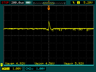
2nd picture shows output from mouser batch and 1st picture shows output at same load from TI batch. I also captured input 5V for reference and is stable. Can you assist me on this?

Thank you,

Emman

 \

  • HI,

    The following are pictures from Mouser

    And these are the ones from TI Store

    Thank you,

    Emman

  • Hi Emman,

    Thank you for the scope shots they are helpful as we try to understand what is happening in this situation. The behavior is very strange the units should behave the same regardless of where the units are distributed from. Below are some questions I have to help understand what is happening. 

    • Are the high points in the output voltage really regulating at 3.5V when these should be 3.3V devices? 
      • Is this just an accuracy limitation of the scope since it is in a 1V scale compared with the 500mV scale of the second plot?
        • If it is really 3.5V is it possible that there is another power rail which has a leakage path to your 3.3V rail
          • maybe the LDO is powering a load with multiple power rails or there is a diode connection between the 3.3V rail and a higher rail (diode could be internal or external to a separate IC)?
          • If you add some load does the output voltage return to 3.3V? 
      • What is the current being drawn from the output of the LDO during these high points?
    • What are these LDOs powering in your application? 
      • Do the dips correspond with a load transient?
  • Hi Kyle,

    Yes it is around 3.5-3.6 peak. No ther is no other sources of power aside from voltage sense point of below 2V. The issue seems to be load related because when the load's bluetooth function was turned off, it regulates properly. It starts to fluctuate when bluetooth is turned on which I relates to as being higher load.

    Another thing to consider is when I tried swapping TLV75733 from previous purchase from Mouser, it regulates properly already even if load's bluetooth function is turned on.

    Im not sure how will I be able to get current waveform.

    Thank you,

    Emman

  • And also, this is repeatable on another 3 copy of product that has been replaced with tlv75733 from previous batch.

  • Just for completeness about two weeks ago Emman and I worked on this privately so schematic and layout files could be shared securely but I wanted to come back and provide the results in case someone comes across this in the future so they know how to address the issue. 

    After reviewing the layout I noticed that the input capacitor was further away from the input pin than was ideal and since this issue seemed to correlate with the Bluetooth turning we speculated that there may be high frequency noise coupling onto the input rail on the PCB. So I asked to re-take the scope shots when the problem is occurring and zoom in on the time scale so we can look for noise around 100 MHz and higher (making sure the probe channel isn't set to filter frequencies above 20 MHz or 200 MHz). 

    Below is the scope shot that was captured showing a high frequency spike.

    Emman then added a 1uF right next to the LDO which eliminated the high frequency spike and eliminated the issue.