This thread has been locked.

If you have a related question, please click the "Ask a related question" button in the top right corner. The newly created question will be automatically linked to this question.

TPS53667: TPS53667 register read error

Part Number: TPS53667

Dear team,

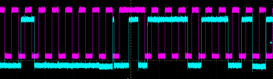
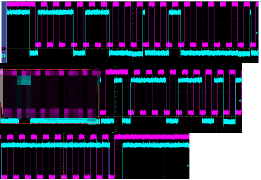
Customer met an issue of TPS53667. When customer read register, all return FF. But the function and power supply are all normal. I did not see any security or protection to register of this IC. Customer have used this IC before and have not met this issue before.

Thanks.

Best regards,

Sammi

  • Hi Sammi, Can you please ask the customer to capture the PMBus CLK and DIO lines so we can see the transaction being attempted?

    Also, please confirm the PMBus address assigned to the device through the ADDR pinstrap resistors. 

  • Hi Matt,

    Thanks for your response. Below pictures is the CLK and DIO data of read command code 10h, the three picture combined together is a full cycle.

    For the address of PMBus set to 0x76, and the external pinstrap setting as below picture.

    Thanks.

    Best regards,

    Sammi

  • Hi Sammie, based on my decoding, the transaction structure looks incorrect. Can you please double check it?

    I see:

    <Start><Slave Address + W><Ack><Command code 0x20><Ack><Command code 0x20><Ack><Repeated start><Slave Address><....> 

    Should be : 

    <Start><Slave Address + W><Ack><Command Code 0x10><Ack><Slave Address + R><Data><Nack><Stop>

  • Hi Matt,

    Thanks. Checked with customer and update the new waveforms:

    Customer also checked the frequency of clock only 2.6K, any special requirement of clock frequency?

    Thanks.

    Best regards,

    Sammi

  • Hi Sammi, 

    I am assuming the pixelated portion of the waveform is just repeated from the top waveform? Assuming that is correct, I think the structure looks OK:

    <Start><Address 0x76 + W><Ack><Cmd code 0x20><Ack><Repeated Start><Address 0x76 + R><0xFF><Nack><Stop>

    It is interesting the device appears to ACK the final data byte and still respond with 0xFF 

    Is it possible to try this with the TI GUI USB-to-GPIO and Fusion Digital Power Designer. ? Can you also scan the bus to see if the device is responding to the expected address? 

  • Hi Matt,

    Customer will test with TI GUI. Customer also have question that the clock frequency of PMBus is 2.6K, is the clock frequency OK for the application?

    Thanks.

    Best regards,

    Sammi

  • Hi Sammie, Low frequency I2c operation should be OK as long as the SMB Clock timeout of 25ms is not being hit (e.g. clock is not held low by master for more than 25ms at a time). I think you said operation is at ~2kHz which should be more than enough.