This thread has been locked.

If you have a related question, please click the "Ask a related question" button in the top right corner. The newly created question will be automatically linked to this question.

BQ29700EVM-610: Auto enable output when new battery is connected, without shorting TP4 to Cell+

Part Number: BQ29700EVM-610
Other Parts Discussed in Thread: LMC555, CSD16301Q2

Hi,

I have bought the BQ29700EVM-610 dev board for developing a battery protection circuit. The battery I will be using later on is a 3.8v LiHV (4.35v fully charged). I plan to replace it with a BQ29702 most likely.

My main issue is that, when I connect a new battery, I must briefly pull up TP4 (DOUT) to battery Cell+ (TP1) to enable the output.

Is there a way of going about not needing to enable the output when a new battery is inserted?

One idea was to implement a LMC555 timer in one shot mode to enable to protection protection IC when a new cell is plugged in,it would paulse the output to trigger on and the safety features would still function like normal, the output would disable if any fault would occur as usual.

Same circuit as shown on page 2:
http://www.ti.com/lit/ug/sluuaz3/sluuaz3.pdf

http://www.ti.com/lit/ds/symlink/bq2970.pdf

Any suggestion to have the output enable automatically when a new cell is plugged in?

  • Hi Vismantas,

    The suggested method in the datasheet is to connect the charger to PACK+ and PACK- or to short V- to VSS to enable DOUT. See the note on the top of datasheet page 16: http://www.ti.com/lit/ds/symlink/bq2970.pdf

    Best regards,

    Matt

  • Hi Matt,

    Yes I did see these notes in the datasheet, but for my application there is no charger that will be implemented, (external charger will be used)The battery will be hot swappable, it would cause an inconvenience. Which is why I raised this question. Without a "charger input", or implementing a reset button that would short V- to VSS to enable DOUT, is there another way you could suggest to auto enable the output when a new sell is plugged in?

    My two implementation options that came to mind would be:

    Implement a LMC555 in one shot mode which would toggle and enable the output only once when a new cell is connected (and protection features will function as normal), the LMC555 would be very low current draw as well.

    Or implement a push button which would short V- to VSS to enable DOUT, which would be inconvenient for every single time a new cell is inserted... kind of clunky. 

    Any other thoughts of implementing a one time enable for the battery IC?


    Or is there another lipo protection chip that is similar just without this whole "short output to enable" on a new cell insert feature?

    Thanks,

  • Hi Vismantas,

    I checked with the designer for this device and he says either of the two ideas you mentioned should be effective. He had no better idea to offer. I don't know of another similar device that would remove this challenge.

    Best regards,

    Matt

  • Matt,

    If I wanted to increase the current limit, how would I go about that? (Say short 5 amps peak).

    I understand that I would need to get the right rated mosfets, but how is the current sense resistor calculated for over current discharge (load) compensation ? I understand that R2 (2.2k) is the current sense resistor going to V- from Pack -?

  • Hi Vismantas,

    R2 is not a current sense resistor since it is not in the current path, so you don't need to change this value. The FET on resistances act as the sense resistor for this device. There is a design example near the end of the datasheet that might be helpful for choosing the correct FETs.

    Best regards,

    Matt

  • Thanks for your help,

    So ok, after reading into more how to IC detects and samples for over current discharge and all that. As well as much better availability. So the bq297002 is what ill stick to, which has a UVP of 2.8v and a OCD of 0.160 V. Given that my boost converter takes upto almost 10 amps on when a new cell is inserted. I figure a 10-12 or so amp cut off limit could be safe? in the datasheet on page 20, In the example, for 5a, they give an upper limit of 7a, they use the bq29700 which has a 0.100v cut off. So 100 mV/7A = 14.3 Ohm (would need for RDS on?).

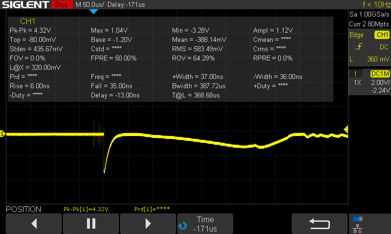
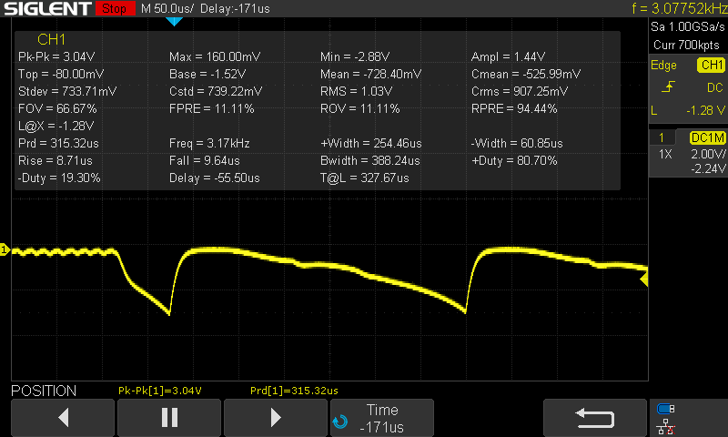
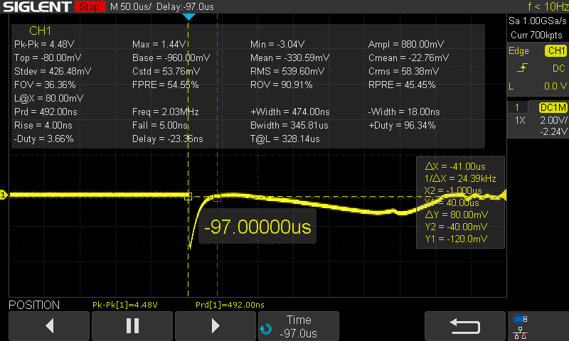
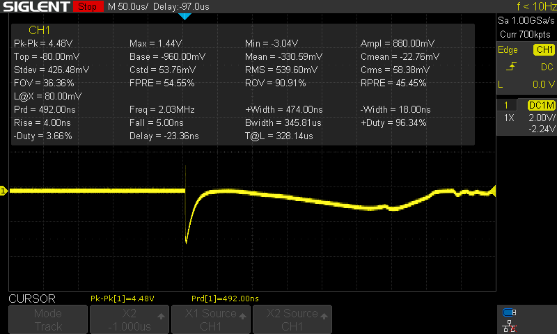
    Also few clip snap shots of the scope when a new cell is inserted, I used 3 1.5 ohm resistor in parallel for a quick test,(0.333 Ohm), and after a little ohms law I got almost 10A (9.369A), for roughly 50 uS, ODC protection kicks in, OCD delay is 16 ms...according to the datasheet.

    So For my application lets take the bq297002, OCD of 0.160v, I calculated about 16 mOhm for my application. (at 10 amps, 160/10)?

    So I should be on the scope out for a low RDS on mosfet of around 16 mOhm? with a low RDSon of like 3v or lower(2.5v? lowest). And most likely will need to double up on the mofest (2 output and 2 input) to get my 10 amps of current? Any suggestions on mosfets?

    For example I was looking into CSD16301Q2, might be a bit over kill:
    www.ti.com/.../suppproductinfo.tsp

    Few other FET's I was looking at as well.

    Alpha and Omega:
    AON2406
    aosmd.com/.../AON2406.pdf

    Rhom RQ6E080AJTCR
    www.rohm.com/.../rq6e080aj-e

    RF6E065BNTCR
    www.rohm.com/.../rf6e065bntcr-e

    RF4E100AJTCR
    https://www.rohm.com/datasheet/RF4E100AJ

    Thanks for your help.

  •     Few pictures of scope input, when a new cell is inserted. Note, used 3x 1.5 ohm 3/4w 1% resistor, 0.333 ohm effective. LTR18EZPF1R50

  • Hi Vis,

    I'm not too familiar with all of the FET options available and new devices are coming out each year, so unfortunately I cannot recommend a selection. Here are some things to consider:

    Look for RDSON at specified Vgs in the range of the cell. Make sure the RDSON is suitable for the load required. One thing to keep in mind is there is variation in FET RDSON, so consider variation with voltage, temperature (check the curve in the FET datasheet), and part to part. 

    Best regards,

    Matt

  • Matt, 

    Thanks for this info, helps me point in the right direction.

    In case I need to look into using 2 FET's in parallel for current handling, Should I be considering the total RDSon resistance as a regular parallel resistor equation ? Rt= 1/R1 + 1/R2?

    Thanks,

    Vis

  • Hi Vis,

    2 FETs can be more complicated. Removing one FET from the path would cut the resistance and variation in half, so it does have that benefit, but I'm not sure if this topology would affect any of the fault recovery. There may be issues that are not obvious at first glance.

    Best regards,

    Matt