Part Number: ISO5852S
Dear sir,
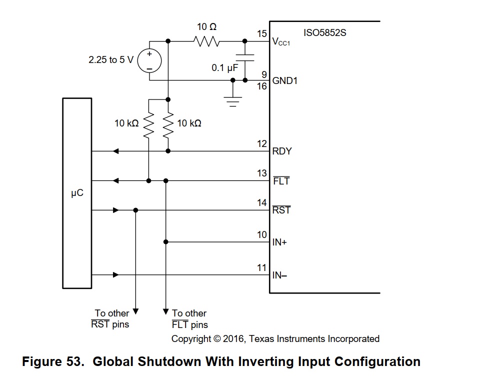
we are using ISO5852s for our inverter and the driver circuit is given below.
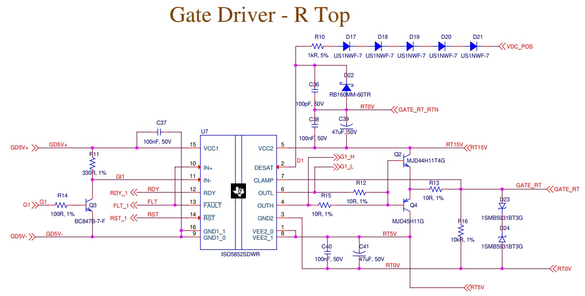
The same circuit is followed for all the six switches in the inverter.
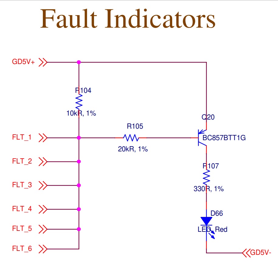
The fault output circuit is given below.
During normal operation, please find the below voltages.
Vcc1 - GDN1 : 4.98V
RDY : 4.28V
FLT output : 3.328V
RDY output : 4.96V
During the normal operation, the fault output is 3.28V. so the BC857 (Q20) always goes to ON state and the fault LED (D66) always in the ON state.
Could you please suggest the suitable procedure to get the 5V output in the fault output and control the operation of fault LED?
Thanks & regards,
Rajasekaran.