This thread has been locked.

If you have a related question, please click the "Ask a related question" button in the top right corner. The newly created question will be automatically linked to this question.

TPS61087: Output voltage of TPS61087

Part Number: TPS61087

Dear all,

I would like to ask about TPS61087.

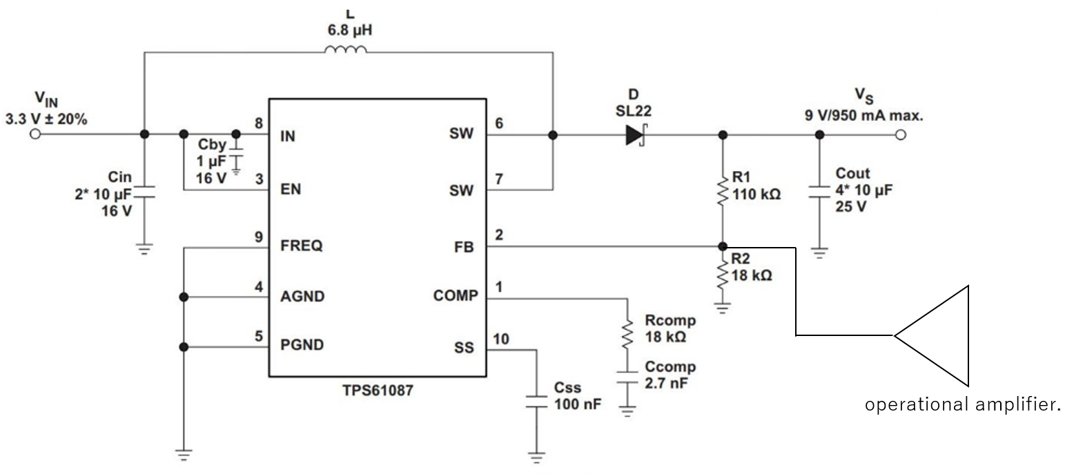
When the output voltage is set from 9V to 8V (setting the values of R1 and R2 to match the output voltage of 8V) using the same circuit as the data sheet Figure.16 (the following circuit), the output voltage only increases to 5V.
(At this time, 330Ω is connected to the load.)

The output voltage remains at 5V even if the following measures (measures to increase the ON time) are taken.
・Lower input voltage than 3.3V
・Try a load of 330Ω or more.
・Replaced the inductor at 4.7, 10, 18, 27uH.

If there are any conceivable factors, please let me know.
When I check the datasheet, it seems that Rcomp and Ccomp need to be set to 8V, but I would like to know if there are other possible factors.

Best Regards,

Y.Ottey

  • Dear Sir,

    I think there has some soldering issue on the board, please remove the feedback resistor and solder it again.

    By the way, what is R1 and R2 value you soldered on the board?

  • Dear Helen

    Thank you for your reply.

    "I think there has some soldering issue on the board, please remove the feedback resistor and solder it again."

    Does the "feedback resistor" shown above refer to R1 and R2 on the circuit?
    Also, could you tell me why you think that the output voltage only goes up to 5V due to "some soldering issue on the board"?

    "By the way, what is R1 and R2 value you soldered on the board?"

    The above is currently being confirmed.
    Is the above question to check if R1 and R2 are set as calculated below?


    Regards,

    Y.Ottey

  • Dear Y. Ottey,

    Please check if the output voltage changes when you start with no load on the output.

    Would you please share the resistor values you are using for R1 and R2?

  • Thanks Brigitte :)

    Hi Ottey,

    Yes, R1 and R2 should be the value calculated by the below equation:  if Vo=8V, R2=17.8k,  then R1=97.6k .   By the way, what kind of board did you use? Is it TPS61087 EVM board?

  • Dear Helen and Brigitte

    Thank you for your reply.

    There are additional things to check.
    When the circuit is confirmed, it is a circuit in which the operational amplifier is connected to the wiring of the FB terminal as shown in the figure below.
    The reason is that I want to change the output of TPS61087 by injecting the voltage from the operational amplifier.

    In this case, will the IC be damaged if voltage is injected from the output of the operational amplifier while the TPS61087 is not started?
    (Detailed circuits can be sent to you in a private message.)

    Regards,

    Y.Ottey

  • Hi Ottey,

    Will not be damaged. But I'm wondering this kind of connection may leads to error.

    It should decoupling the output of amp and the FB. a RC filter is needed before connecting to the FB.  And the amp should be connected as a voltage follower.

  • Dear Helen

    Thank you for your reply.

    "It should decoupling the output of amp and the FB. a RC filter is needed before connecting to the FB.  And the amp should be connected as a voltage follower."

    When I checked the circuit, it was as follows

    ・ There is no RC filter between the FB terminal and the output of the amplifier.
    ・ The part with the amplifier is a non-inverting amplifier circuit (calculated the amplification factor is 5.1V / V)
    What kind of error is possible in this case?
    (If all goes well, I'll send you a detailed circuit in a private message.)

    Regards,

    Y.Ottey


  • Dear Helen

    I have an additional question for you.
    "And the amp should be connected as a voltage follower."

    Please explain the reason why the peripheral circuit of the amplifier is used as a voltage follower as described above.

    In addition to my previous post, I would be happy if you could answer.

    Regards,

    Y.Ottey

  • Hi Ottey,

    The part with the amplifier is a non-inverting amplifier circuit (calculated the amplification factor is 5.1V / V)? could you please send the related circuit to me?

  • To decoupling the circuit, or its hard to get the target voltage.  But anyway, I need the exact circuit for a study.

  • Dear Helen

    Thank you for your reply.

    I will send you a detailed circuit with a private message.

    Regards,

    Y.Ottey

  • OK! Please close this post.