This thread has been locked.

If you have a related question, please click the "Ask a related question" button in the top right corner. The newly created question will be automatically linked to this question.

BQ25883: How to get the temperature of battery

Part Number: BQ25883

Dear experts,

My Schematic is as below,

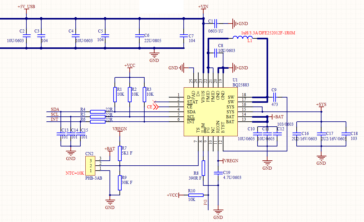
In my design, I need to obtain the temperature of the battery.

The type of NTC of the battery is 103AT-2. The relationship between the temperature of NTC and the resistance value, for example, 0 ℃ corresponds to 27.278k Ω, 10 ℃ corresponds to 17.958k Ω, 20 ℃ corresponds to 12.091k Ω, 25 ℃ corresponds to 10K Ω, 30 ℃ corresponds to 8.313k Ω, etc. TS as percentage of REGN reading can be obtained in 8.5.34 and 8.5.35 of bq25883 datasheet. NTC is connected in parallel with R9, and then connected in series with R7 resistor, the relationship is Rntc / / R9 / (Rntc / / R9 + R7), which can also get TS as percentage of regn reading, and finally divided by 0.098%, it can be compared with registers REG21 and REG22.And I read the value of REG21 and REG22 as 0x02B1.In the table of temperature and resistance conversion, this value represents 10 ℃ - 17.958k Ω, but the resistance of NTC measured by fluke multimeter is 9.66k Ω - 25 ℃. What's the problem? There is also a calculation of resistance in 8.3.7.4.1 JEITA guideline compliance in charge mode. Is there any problem in the selection of resistance value in my schematic? How to convert the resistance and temperature conversion table and registers REG21 and REG22?

  • And I find a problem about the formula about RT2 in 8.3.7.4.1 JEITA guideline compliance in charge mode.VT1=VREGN* 73.25% = 3.516V,

    VT2=VREGN*34.375%=1.65V,VREGN=4.8V,

    In my calculations, RT2=1.44KΩ,it's a negative number, not in the text RT2= 5.24KΩ.Why is that?


    Thank you.

  • To start, I would recommend by taking a look at the below link. This Application Report does a good job of converting the TS% (which is a decimal here no larger than 1) to the temperature of the battery. Please note that you need to know the thermistor's resistance at a reference temperature and the thermistor's beta value.

    http://www.ti.com/lit/an/slua745/slua745.pdf

    For your second post, what temperature range are you looking for? I could assist better if I knew what your desired operating temperature range is.

    Thanks,

    Mike Emanuel

    Please click "This resolved my issue" button if this post answers your question.

  • OK.I misunderstand the value of VT1 and VT2,which is a decimal no larger than 1.I need to measure the temperature range between 0~60 ℃.

    Thanks.

  • Assuming you want to operate at full charge current and regulation voltage between T1 and T5, which would be between 73.25% and 34.375% of REGN, you would follow the calculation in Section 8.3.7.4.1. For a temperature range of 0C to 60C and a 103AT-2 thermistor, the resistor from REGN to TS would be 5.24 kOhm and the resistor from TS to ground would be 30.31 kOhm.

    If you desire to start full charge current at T2, you would use the equations in Section 8.3.7.4.1 accordingly to recalculate the resistor divider.

    Thanks,

    Mike Emanuel

    Please click "This resolved my issue" button if this post answers your question.

  • OK.Do I have to set the value of RT1 and RT2 in strict accordance with the resistance values in BQ25883 Datasheet? I only have 5.1k Ω and 30K Ω here. At the same time, according to your suggestion, I calculated that the β value of thermistor is 3420, T= 85 ℃, T0 = 25 ℃, and then converted to Kelvin temperature.

    Thanks.

  • You do not have to set RT1 and RT2 in the datasheet as different systems will have different thermistors. However, if you are using the same thermistor in the datashseet and desire the same operating range, the datasheet resistors will work.

    Otherwise, you will need to calculate the value of your thermistor at the desired minimum and maximum temperature you intend to charge at, and you will need to use the equations in Section 8.3.7.4.1 in order to calculate the new resistor divider.

    Thanks,

    Mike Emanuel

    Please click "This resolved my issue" button if this post answers your question.

  • OK.I desire charge status:0℃~15℃ --- Charging current = 200mA ,and 15℃~45℃ --- Charging current = 500mA .


    Thanks,

    Victor

  • and no charge at any other temperature.

    Thanks,

    Victor

  • Dear Victor,

    With just using two resistors, it is difficult to program the desired settings. What I would recommend is to set VT1 to VT5 for 0C to 45C. This yields a RT2 of 173.377kOhm and a RT1 of 8.949kOhm. Outside of this range, charge will be suspended.

    To accommodate your desired charge currents at each temperature, you will need to use the ADC. The ADC will tell you what percentage of REGN the TS pin is. In order to use this data, you need to do some calculations to see what the TS percentage will be at 15C. Then, you would use the microcontroller controlling the charger to change the charge current at this temperature. Some hysteresis would be helpful to prevent you quickly switching between a charge current of 200 mA and 500 mA when you are right at 15C.

    Thanks,

    Mike Emanuel

    Please click "This resolved my issue" button if this post answers your question.

  • Dear Mike,

    Thank you for your recommendation.I will do it .

    Thanks,

    Victor