This thread has been locked.

If you have a related question, please click the "Ask a related question" button in the top right corner. The newly created question will be automatically linked to this question.

BQ25883: Noise in Inductance

Part Number: BQ25883
Other Parts Discussed in Thread: BQ25887,

Hi TI team,


         We found that there are some noises in inductance after removing the battery from charge circuit. And at this point . The Vbus has powered the system (100mA load) sequentially. The phenomenon can find both in TI BQ25883 EVM and in our own bq25883 board. In the process of noise . The out-of-audio is in active and can TI help to guide how to solve the issue ? Thank you! 

         The following picture is the convert waveform in the process of noise. 

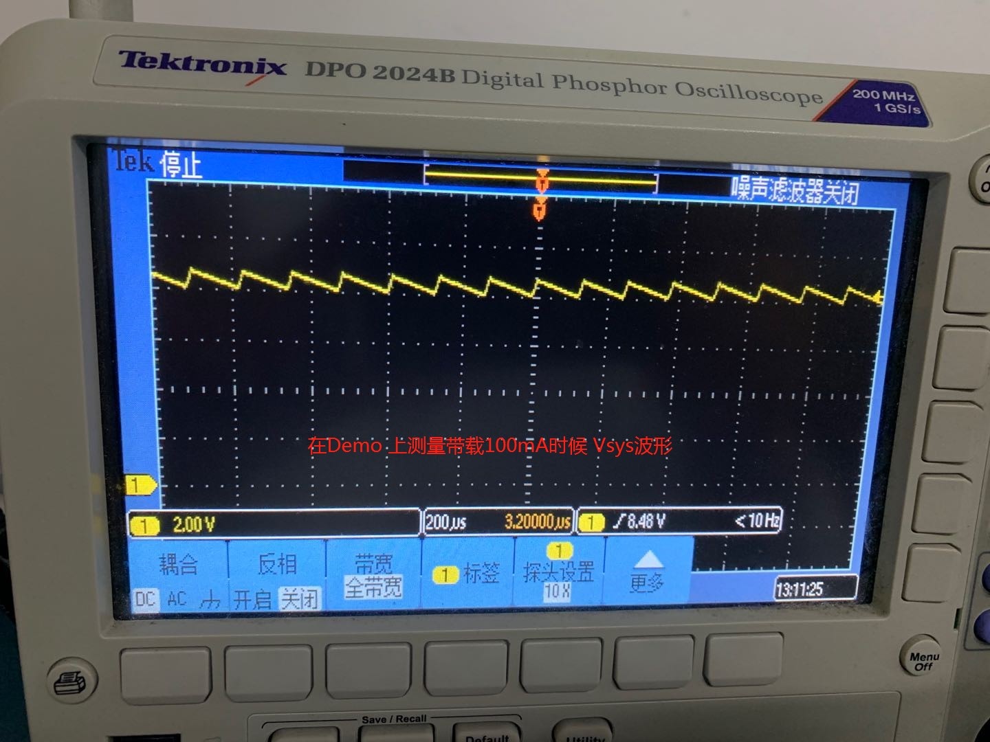
                                                                                                                       Picture.1 The waveform of Vsys

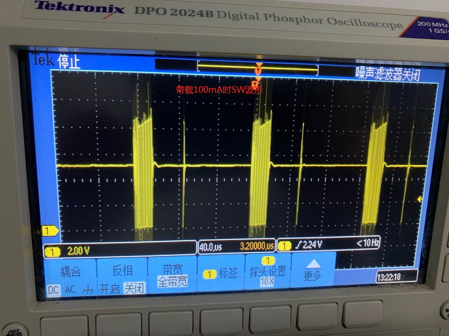
                                                                                                                   Picture.2 The waveform of SW

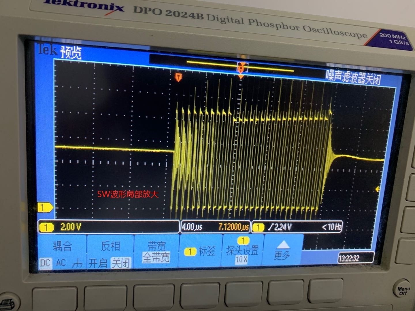
                                                                                                                                 Picture.3 The waveform of SW

  • Dear Troyson,

    The first figure is demonstrating the charging and discharging of the BAT pin. Although there is no battery, there is still 10 uF of capacitance on the BAT pin and 44 uF on SYS. First, the charger charges the part to regulation battery voltage, approximately 8.4 V in your case. It does this quickly because the capacitance is so low compared to the capacitance of a real battery.

    Because the voltage of BAT is above MINSYS and charging is terminated, the SYS pin will be about 50 mV above the BAT pin. However, the SYS pin is still well above MINSYS, so the charger will not turn on to refresh it. In order to get the 100 mA of current, it draws from the BAT pin through D7 on the EVM.

    Once the BAT pin drops below the recharge threshold, the converter turns on to charge the output capacitance at BAT and SYS again. This brings BAT up, and SYS follows BAT up, albeit slightly above. This explains the triangular waveform you see on SYS.

    The waveform of SYS you are seeing is the PFM mode. As said above, the charger is turning on and off as dictated by the size of the output capacitance and the draw of the SYS load. PFM is used for light load and 100 mA SYS load with no battery charging qualifies.

    Thanks,

    Mike Emanuel

    Please click "This resolved my issue" button if this post answers your question.

  • Hi Mike ,


          Thank you for your great support. We have verified the cause and It really be caused by frequency of charge-discharge from output capacitor.

          Then we added the capacitance value of output capacitor and it can reduce the frequency but the frequency it's still high(>7khz). So that we do not think add the capacitance value of output capacitor can solve this issue .

           Do you have another suggestions ? Thanks !

  • Dear Troyson,

    The key here is that you removed the battery charger from the circuit. The charger does not know that you removed the battery, and will treat the uF order level output capacitance as the battery and charge it as fast as you desired to charge the battery. It will discharge it through your system load and continue to do this "oscillatory" behavior until a real battery is inserted and a more "normal" charging cycle can start.

    I guess my question to you is, do you intend to use this part to charge a battery, or just the approximate 55 uF of output capacitance? Do you intend to remove your battery?

    Thanks,

     Please click "This resolved my issue" button if this post answers your question.

  • Hi Michael,


               We want to charge the battery . But we has other battery guage circuit and the guage circuit will turn off the extra mos automatically(we added extra mos between charge circuit and battery ) while the capacity of battery exceed 95% . So can you help to tell us how to solve the issue ? Thank you!

  • Dear Troyson,

    Why do you have this extra MOS between the charge circuit and the battery? The battery needs to be connected to the BAT pin to avoid this issue. You can still use the gauge information to communicate to the charger to disable charge.

    Thanks,

    Mike Emanuel

     Please click "This resolved my issue" button if this post answers your question.

  •  Hi Michael ,

            Sorry,This is my customer's product. I do not know why they added this mos.

            And As you said -You can still use the gauge information to communicate to the charger to disable charge.

            Can you tell me  how to BQ25887 to disable charge? Thank you!

  • Troyson,

    For the bq25883 and bq25887, they can disable charge via I2C.

    Thanks,

    Mike Emanuel

     Please click "This resolved my issue" button if this post answers your question.

  • Hi Michael ,


             I have seen two bits which may terminate charge instantly

            1#. Write 0 to REG06_BIT3 (Chage disable)

            2#. Write 0 to REG05_BIT7(Disable termination)

            Because the functional description of the above bits is similar.Can you tell me which one can terminate the charge instantly?

    Furthermore , If I terminate the charge via the above bits . Can converter continuely sequentially convert to power the Sys while there is a load in SYS?

  • Dear Troyson,

    Writing 0 to REG06_BIT3 will terminate charge. The other bit controls a feature called termination, which has to handle at what current, if any, the charge current stops. Disabling termination will not terminate the charge current. Rather, as the charge current decreases in the Constant Voltage mode, this setting will determine if charge stops when the termination current register setting is reached (Termination Enabled) or if it will continue until it the charge current is 0 A (Termination Disabled). For more information on what termination is, see Section 8.3.7.3 of the datasheet.

    You are correct. If you terminate charge, the converter can still power SYS while there is a load on SYS.

    Thanks,

    Mike Emanuel

    Please click "This resolved my issue" button if this post answers your question.

  • Hi Michael,

             Thank you! The charging can be stopped now and the noise disappeared. But there are still three issue we meet again.

             1.The Ichg offset seems to be 0mA rather than 100mA which mark in the specification


             2. We found the Vsys is inexact when we disable charge in both of EVM & our borad. In our test. The Vsys is 6.98V (with 100mA load) while the SYS_MIN is 6.8V which set in REG07

             3. We found the charge efficiency is too low in our board (Vin=5V/Ichg=960mA/Isys=30mA). Do you help some suggestions to improve the efficiency

            Thanks!

  • Dear Troyson,

    Can you please post this issue in a new thread and mark the posts that answered your questions resolved? In order to generate more knowledge for our customers, it is more helpful to break down threads by individual problems. Otherwise, each thread is not separated by topic but by customer. This makes it hard for other customers to find resolution to their problems. I will be able to answer the question in the new post.

    Thanks,

    Mike Emanuel

  • Hi Michael,

            Thank and got it. I have open a new topic about the new issue. Can you help to solve it ? Thank you !

            The new topic link : https://e2e.ti.com/support/power-management/f/196/t/893988