This thread has been locked.

If you have a related question, please click the "Ask a related question" button in the top right corner. The newly created question will be automatically linked to this question.

ISO5851: RC Filter on the Power Rail

Part Number: ISO5851
Other Parts Discussed in Thread: ISO5451, TIDA-00638, TIDA-00446, , UCC21530-Q1, SN6505A

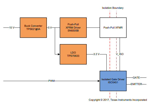
I am referring to the suggested circuit for the ISO5851 gate driver proposed in reference design TIDA-00446 and the very similar circuit proposed for the gate driver ISO5451 in reference design TIDA-00638.

Both designs place an RC filter in series with the power supply to the low voltage side of the driver.  I have always made use of low impedance ground and power planes when supplying ICs so the notion of deliberately placing a relatively large resistance into the power supply path seems strange.

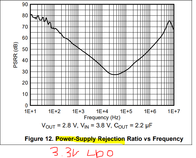
I expect this would serve the dual purpose of preventing noise from entering the gate driver from the power supply while also preventing noise from the gate driver from propogating back into the rest of the system. The application note simply says "An RC filter filters the 3.3V rail". I am in the midst of a design using the UCC21530-Q1 and I am considering whether to include a similar RC circuit. I would prefer to use a 5V power supply and I am concerned about blindly copying the component values for a different supply voltage.

Are you able to shed any light on the inclusion of this circuit and how the values are selected?

  • Hi Euan,

    This is a really good question.

    The RC filter in both designs uses 10ohm resistor/0.1uF cap, so the 3dB cutoff frequency is ~160kHz, and the 0.1uF cap serves double duty as the bypass capacitor for the input side of ISO5451 and ISO5851.

    The buck converters supplies both the LDO (used for input side on gate driver) and the SN6505a push-pull converter used for the high-side drivers. 

    This push-pull converter operates at ~400kHz. By its nature as a transformer-based switching converter, it could necessarily cause some interference on the 5V line, especially since it supplies the output-side of the gate drivers, which have high peak current draw.

    So, SN6506a could inject some interference at ~400kHz (it operates 350-420kHz) onto the 5V rail that supplies the LDO. Why would the LDO pass it through? Unforunately, the LDO has a pretty poor PSRR at these frequencies of around 30dB, pretty bad.

    ISO5451 and ISO5851 can both operate in the same frequency range that SN6505a push-pull converter does, so they want to make sure that the 3.3V supply is filtered to attenuate those frequencies, because its not super capable to do it on its own. You don't want your 3.3V supply rippling at the same frequency as your inputs!

    Thats the reason they are using an RC filter. The cutoff-frequency of 160kHz was chosen based on the main source of interference, which in this case is SN6505a push-pull converter. You want the filter cutoff to be <=1/2 of the expected ripple/interference. 160kHz is less than half of SN6505a's operating frequency range (350-420kHz), so thats good.

    I think that they just used the standard recommended bypass cap size and selected the resistor from that. More than likely, they just wanted to use nice round numbers which is why 10Ohms was used rather than 7,8, 9 etc. You would not want a very high resistance so you dont drop the DC voltage very much.

    If in your design, you know exactly the input switching frequency to the gate drivers and its not close to ripple frequency you expect, then you most likely do not need an RC filter in your design. In these reference designs, its a general design where they don't know how the user's input frequency, so they put it there just in case the user wants to operate at higher frequencies.

    Because the RC filter incorporates the decoupling capacitor, its really only one extra footprint on the PCB for each driver. If you are concerned that you may or may not want an RC filter, you can always put the footprint there and populate it with a 0ohm jumper, and change to a resistor later if you see the need.

    Another option to ensure a clean supply to your gate driver input is to select an LDO that maintains high PSRR across the ripple frequencies to reject the ripple.

    I hope this helps. If this answered your question, let me know by pressing the green button. And if you have any more questions, please let us know!

    Best

    Dimitri

  • Thanks for this very speedy and detailed response. I don't intend on switching anywhere near 400kHz so it looks like I will get away without the RC filter. I will be revisiting my choice of LDOs throughout the system to check their PSSR at this frequency. I had already constructed a test board using the SN6505 and had noted some switching frequency ripple on my 5V rail.

  • Euan, youre welcome!