This thread has been locked.

If you have a related question, please click the "Ask a related question" button in the top right corner. The newly created question will be automatically linked to this question.

UCC21530: Using a voltage regulator to power the UCC21530 driver.

Part Number: UCC21530

Hi,

I'm using a UCC21530 for a university project for a buck converter to convert 500V to 200V.

I'm trying to power a UCC21530 using a linear voltage regulator for VCC, VDDA and VDDB.

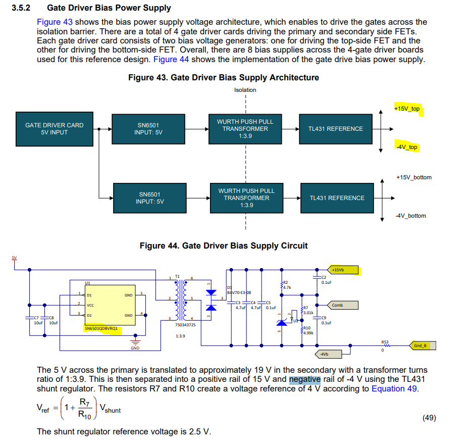
My design is for the converter is based on figure 39 of the datasheet:

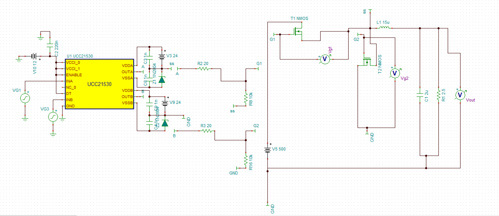
The design is working fine without the linear regulator.

I'm trying to use a TPS7A4501 to regulate the Vdd and Vcc, but I cannot figure out how to use it since the zener is connected to the negative side to the voltage supply and the regulator only has one output pin.

I have tried several ways to connect it but none have worked. This is my current schematic:

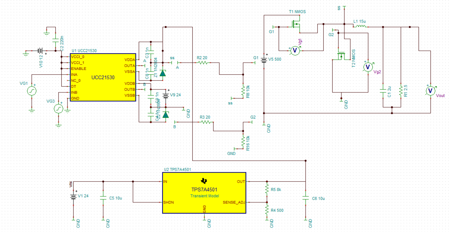
NMOS_buck_zener - autosave 20-03-26 23_16 - autosave 20-03-28 13_55.TSC

What should be the correct was to insert a voltage regulator in this design?

Thanks,

  • Mukund,

    Good question. You are correct - the setup with the LDO will not turn on NMOS "T1" at all because the 20V will be referenced to ground, unable to provide a positive bias to highside NMOS T1.

    So the question is how to implement the "floating" 24V DC source supplying VDDA, referenced to the source of T1. 

    One way is to use a bootstrap circuit which is very simple and low-cost to implement. This is shown in the datasheet here.

    The bootstrap charges the cap Cboot on high-side input's off-cycle, and Cboot swings VDDA up on the high-side oncycle, referenced to switch-node/source of Highside nmos, T1 in your case.

    A good resource on selection of bootstrap components is here.

    There are examples for UCC21530 to be used with bootstrap along with zener for negative bias, but it is more tricky and it points out that it is best for 50% fixed duty-cycle designs.

    Another option is to use transformer-based push-pull converter such as SN6505Bto generate bipolar supply without the limitations of the circuit above.

    An example is in our TI reference design with this IC, located here, which uses SN6505 to generate the bipolar power supplies.

    The power supply design is shown on page 41 section 3.5.2, and you can see it takes care of the negative supply rails AND also generates the isolated supplies from the low-voltage 5V, which you may or may not need for the purposes of your simulation..

    Note that this also generate the isolated bias power supply (in your case the 24V VDC supply), so its a good idea to look at it.

    The low cost and simple option is bootstrap, but its best if you don't need the negative turn-off bias. I saw that you are using the PSPICE NMOS models. If you know what MOSFET you plan to use in your final design, you can check in the datasheet to determine if you even need to provide the negative turn-off bias. This could help simplify your circuit.

    I hope this helps. If this answered your question, please let me know by clicking the green button. And if you have any further questions, don't hesitate to reach out.

    Best

    Dimitri