This thread has been locked.

If you have a related question, please click the "Ask a related question" button in the top right corner. The newly created question will be automatically linked to this question.

UCC28950: UCC28950 TINA TI Steady State Reference Design Simulation

Part Number: UCC28950
Other Parts Discussed in Thread: PMP8740

Hello Dear Experts,

I am working on UCC28950 Steady State Reference Desing  simulation and I try to simulate  my 2kW  dc dc converter design using this reference design simulation.

Here I have a question about UCC28950 Steady State Reference Desing .

- In the output of dc dc converter, there are output inductor(Lout) and capacitors(Cout). These capacitors and inductor have IC value . For example , (Lout= 2U DCR=0.75M IC=20

-What is the IC ?

-What is the importance of IC value for bobin and capacitors?

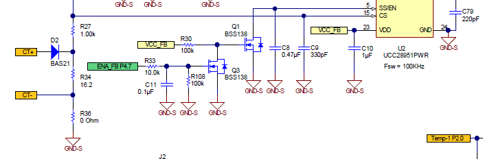
I attached below related circuit picture from  UCC28950 Steady State Reference Desing  simulation circuit.

  • Hello Bilgin

    In this context 'IC' means Initial Condition. This is the value that the simulator assigns to the component at the beginning of the simulation. It means that the simulation gets close to its steady state condition more quickly than it would if the initial condition were set to zero.  Normally one would set the IC for the capacitor to be the regulated output voltage and the IC for the inductor to be the load current.

    Regards

    Colin

  • Hello Colin

    Thanks for your reply.

    For example , in my 2kW  dc-dc converter design at full load output is 32V ,62 A.

    -In this case my Cout capacitor has IC=32 , at full load my Lout bobin has IC=62 . Is it OK?

    Also,when I simulate the transformer in steady state solver , this simulation results are changes and results(Vout,Iload) nearly equals to zero.   

    I know UCC28950 model is transient model and it can be simulated in transient mode but, I have a question.

    - How can I simulate this circuit correctly  in steady state solver or steady - state mode?

    Thanks.

  • Hi Bilgin

    Your IC values are correct -

    I'm not sure what you mean about simulating the transformer - can you post your sim file here and I'll have a look at it.

    Regards

    Colin

  • Hi Colin

    I wrote 'transformer' by mistake . I wanted to write "Circuit" instead of 'transformer'. Sorry .

    I am working on PMP8740 reference desing dc-dc converter circuit. I want to simulate this circuit and understand working principle.

    I used almost the same values in PMP8740 dc-dc converter circuit schematic except for voltage and current loop .

    Also, Using this simulation I want to learn full bridge main transformer technical specs. Now, in simulation output voltage about 24 volt and output current is about 44 amper at full load. But my expectation is 32V and 60A at full load. 

    What is this circuit problem I don't know. 

    I attached my simulation file. 

    Please can you help me ?

    Thanks.2kW dc-dc converter.TSC

  • HI Bilgin

    I've been able to run your sim file and it looks like the controller is running in current limit. COMP is high which is due to the output voltage not being at the set point. I reduced the CT burden resistor form 22R to 11R and the output voltage increased significantly but only to about 28V. (I changed the reset resistor (R2) from 4.8k to 1k too.

    I'll continue to work on this but it's slow because I can't spend 100% of my time on it.

    The basic message is that this sim can be made to work, we just need to do a bit more debug on it.

    Regards

    Colin

  • Hi Colin

    Thanks a lot for your help .

    I understood the problem . I changed the resistor values and I saw the your results.(Vout=28V approx , I load= 53A approx)

    I am also working on simulation.  If I get  important changes in results , I will get back to you.

  • Hi Bilgin

    I noticed that the inductor IC doesn't work - it makes no difference whether you set 60A or 0A. I also think that the loop response is relatively slow so you see some damped oscillations in the output - you may want to look at the sim from 9ms to 10ms rather than 500us to give it time to settle down.

    I reduced the dead times you were using to the minimum value because the original values were significantly reducing the available duty cycle.

    Changed R3 from 49.9k to 13k. DELAB time was 1us.
    Changed R4 from 49.9k to 13k. DELCD time was 1us.
    Changed R4 from 49.9k to 13k.

    I increased the input and output capacitances proportionally - this didn't make much if any difference

    Increased C2_2 from 0.47u to 1.5u
    Increased C3_2 from 330u to 1000u
    Reduced R1_2 from 22R to 7R
    Reduced R2_2 from 4.87k to 700R

    The system seemed to be locked out at Dmax so i reduced the primary turns from 19 to 17 get more volts on the secondary. This may or may not be needed but it didn't help.

    The primary leakage inductance should be reduced because the primary current at 1600W is 2.5 times greater than at 600W (EVM) to keep the time needed to reverse the primary current when the primary changes polarity - (dt = l di/V)
    Changed L2 from 10uH to 1uH and DCR from 0.2 to 0.002  - this helped a little.

    The IC for the inductor models seems not to work - the workaround is to run the sim for longer
    Set IC for L2 to 0

    For some reason I don't seem to be getting Dmax even although COMP is locked high (at around 4V or so) which would normally generate Dmax. I'm going to look at that now.

    Regards

    Colin

  • Hi Bilgin

    I checked that the controller model will run from Dmin to Dmax so there should be no reason why it is the cause of the problems. I't suggest that you double check the component values - especially those of Lout and the current transformer burden resistor. You should also look at the values of leakage inductance in both the shim inductor and the transformer primary. The leakage inductance determines how long it takes for the current in the primary to switch direction when the transformer primary polarity changes. No energy is transferred from primary to secondary during this process and it can be a significant part of the duty cycle.

    You will almost certainly need to run the sim out to 10ms or maybe even longer to allow Vout to settle at its final value -

    Monday is a public holiday in Ireland - I'll be back at work on Tuesday 14th.

    Do please let me know how you get on.

    Regards

    Colin

  • Hi Colin 

    Thanks a lot for your valuable informations.

    I changed dead times , input and output capacitances and L2 values according to your values . I looked at the sim file 9ms to 10ms time period.

    Finally , output voltage is between 31.36 V and 31.42 Volt and Load current is between  59.28A  and 59.37A.  I've been able to run my sim for my desired

    output voltage and current level.  Thanks for your help. 

    As far as I understood , the main problems are in Lout , current burden resistor and both the shim inductor and the transformer primary leakage inductance.

    In PM8740 dc- dc converter schematic ,  CT burden resistor is 16,2 ohm and reset resistor  is 100k. When I used these values output voltage and load current are significantly reduced. 

     I have question about CT burden resistor and reset resistor . How do you  calculate  CT burden resistor 7R  and reset resistor 700R values?

    Also , Full bridge transformer and shim inductor are custom design  transformers and  I have no informations about their leakage inductances.

    How can I adjust these values ? 

    I attached the my sim file results and pmp8740 dc-dc converter currrent sense transformer circuit below.

    Thanks.

      .


  • Hi Bilgin

    It's great that you have made some progress. I put in 7R as a burden as a guess to get the sim running and it worked. I'm still trying to figure out a couple of things - and I'll post here later. If you get a chance, can you post your sim file here too so that I can run it for myself.

    Thanks

    Colin

  • Hi Bilgin

    I think there may be a problem with the MOSFET models - I was getting very large input currents and having problems getting Vout to be correct with reasonable accuracy. I changed the MOSFETs for voltage controlled switches and replaced the SRs with diodes. The sim now works - I attach the sim file. Here are a couple of screen shots too - Vo is ok, the output inductor waveform is ok as is the primary current. The dead times may not be optimum but that may be a fuction of the switches - you might want to add 200pF across each of them.

    I'm not sure that the loop is completely stable - you can see that COMP is following a curve - possibly part of a damped sinusoid.

    /cfs-file/__key/communityserver-discussions-components-files/196/2kW-dc_2D00_dc-converter_2D00_2.TSC

    I'm going to put this to one side for now. Please let me know how you get on and if you have any further questions.

    Regards

    Colin

  • Hi Bilgin

    I'm going to close this thread - if you wish you can open a new linked thread to continue on this topic.

    Regards

    Colin