This thread has been locked.

If you have a related question, please click the "Ask a related question" button in the top right corner. The newly created question will be automatically linked to this question.

UCC27710: About operation.

Guru 10385 points
Part Number: UCC27710

Hi team.

My customer uses only high side of UCC27710.

However, it starts and stops repeatedly.

Could you tell me what kind of factor causes it to stop?

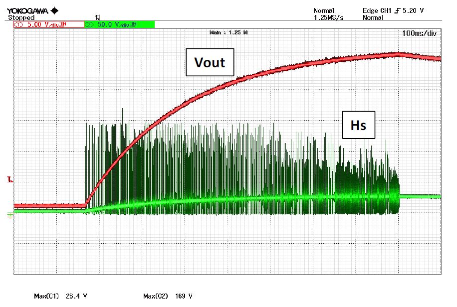
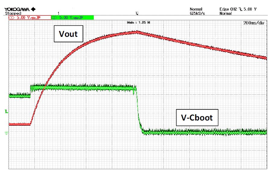
The waveform is follow.

Vout is across the capacitor.

If you need additional waveforms, please let me provide details.

Sincerely.

Kengo.

  • Hello Kengo,

    Thank you for supporting the UCC27710 with your customer. It looks like there is an issue with the HB-HS high side bias maintaining voltage during the long periods.

    The boot capacitor is charged from VDD when the switch node switches to ground, since this is a high side only driver there is no low side FET to guarantee the switch node will switch close to ground. Depending on the power train loading, the switch node may transition to ground or may not.

    To minimize the HB bias drop, make sure there is not a low value gate to source resistance on the high side FET, this will discharge the HB capacitor when the HO is high.

    Refer to the UCC27710 datasheet section 9.2 to size the HB-HS capacitor based on the MOSFET and lowest switching frequency.

    It will help to see the HS waveform to see if it is switching close to ground.

    Regards,

  • Hi Richard.

    Thank you very much for your kind instruction.

    My customer used the diode for low side.

    So, HSpin is at GND level.

    They reviewed the boot capacitor and changed it to 0.22uF.

    However, it will start and stop.

    Could you give me your advice?

    Sincerely.

    Kengo.

  • Hello Kengo,

    Thank you for the update. The first thing to confirm, is to monitor the HB-HS bias voltage with a differential probe and confirm the HB bias is always above the UVLO threshold. We recommend an operating voltage of 10V minimum from HB-HS, the voltage should be maintained above 8.5V to avoid UVLO possible shutdown.

    Does the boot diode have some resistance in series? Confirm the boot diode resistance, if the resistance is too high it may prevent proper HB capacitor charging. We ususally recommend a 2.2 to 10 Ohm range as a typical value.

    Regards,

  • Hi Richard.

    Thank you for your comment.

    I got the waveform that is the HB-HS(=V-Cboot) bias voltage with a differential probe.

    There is sufficient voltage, but it has turned off when the target voltage is reached.

    And then, the Rboot already used 2.2Ω.

    Are there any other comment you care about?

    Sincerely.

    Kengo.

  • Hello Kengo,

    It looks like at a certain point the HB-HS capacitor is not being recharged and drops to 0V.

    Can you confirm with the HB-HS differential probe as in the last plot, and add the HS switch node to confirm the supply is switching, and the UCC27710 HI driver input to see if the controller is stopping the switching operation? It may be that the controller is stopping switching, for some reason, or maybe the switch node stops switching close to ground, which may happen in certain load conditions.

    Regards

  • Hi Richard.

    I confirmed the waveform(bellow), but it also stopped switching.

    Is there any reason why switching stops?

    Sincerely.

    Kengo.

  • If the VDD is above the UVLO threshold, HB-HS is above the UVLO threshold, and the driver input is active the driver output should respond.

    It does look like the switch node is going close to ground based on this plot, but can you also confirm, that the controller is providing the signal to the driver IC when the driver switching stops. That is one signal I want to confirm.

    Regards,