This thread has been locked.

If you have a related question, please click the "Ask a related question" button in the top right corner. The newly created question will be automatically linked to this question.

TPS61087: LED PWM dimming using TPS61087

Part Number: TPS61087
Other Parts Discussed in Thread: PMP15037

Dear all

I would like to ask questions about LED PWM dimming using TPS61087.

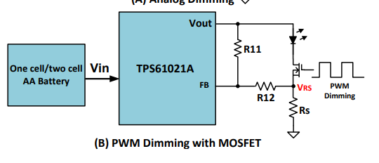
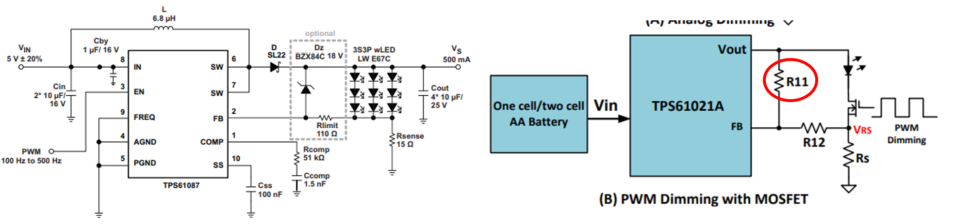
Our customer is trying to do LED dimming by inputting a 200Hz pulse signal to the EN pin as in the following application example (listed in the TPS61087 data sheet).

I would like to know about the following contents.
①By checking the above circuit example, I think that the above dimming is possible.

Is this possible even if the conditions such as input / output voltage change?
* By the way, our customers are trying to implement under the following conditions.
Vin = 3.0V-4.2V
Vout = 6.5V (or 6.0V)
Iout = 1.0A
Fsw = 650kHz

② Is there any concern when dimming the LED by inputting a pulse signal to the EN pin as in the above circuit example?

(I think it is necessary to pay attention to the responsiveness such as making the value of Rcomp larger than the calculated value of the data sheet.)

Best Regards,

Y.Ottey

  • Dear Sir,

    It is very corner.  They need to choose a very small sense resistor Like 0.1-0.2 ohm. So can't output such big current.

  • Dear Helen

    Thank you for your reply.

    "It is very corner.  They need to choose a very small sense resistor Like 0.1-0.2 ohm. So can't output such big current."

    If you place Rsense as you say, what is the maximum output current that is possible under the following conditions?
    Vin = 3.0V-4.2V
    Vout = 6.5V (or 6.0V)
    Fsw = 650kHz

    Regards,

    ]Y.Ottey


  • Dear Sir,

    It is 1A maximum based on >85% efficiency.

    If the efficiency is lower than 85% because of bad layout , poor inductor, then only 0.8- 0.9A maximum depend on the efficiency.

    You can refer to the TI design PMP15037 for the circuit  design.

  • Dear Helen

    Thank you for your reply.

    I have additional questions.

    " They need to choose a very small sense resistor Like 0.1-0.2 ohm"

    You are saying that you need to place 0.1 to 0.2mΩ on Rsense to output 1A as above.
    However, if 1A flows to Rsense 0.1 to 0.2Ω, the voltage applied to the FB pin will be 0.1 to 0.2V.
    This conflicts with the FB pin voltage of TPS61087 typ 1.238V.

    Please explain why Rsense needs 0.1 to 0.2Ω.
    (I would be glad if you could share any reference material.)

    Regards,

    Y.Ottey


  • Please check the calculation in the PMP15037.

    They need to change the circuit similar to PMP15037. Need to re calculate the dividing resistor and Rlimit.

  • Dear Helen

    Thank you for your reply.

    I have a question about the calculation in PMP15037.
    1. I think that the dimming at the EN pin this time can be calculated by the resistance value in the circuit example below. Is this correct?

    (I think that R12 = Rlimit and Rs = Rsense.)

    ※ There was no circuit example for dimming with the EN pin on the PMP15037.


    If the question in 2.1. Is OK, there is no R11 in the application example in the datasheet. Do you need this resistance?

    Also, what happens to the calculation of R12 and Rs when R11 is not needed?

    3. Is the Rsense value as small as 0.1 to 0.2Ω when the LED in the circuit diagram of the TPS61087 data sheet Figure.21 is replaced with one LED with Vf = 6.15V and If = 1A?

  • Hi Ottey,

    The aim of PMP15037 is to reduce the loss across the Rsense, without R11, the voltage across Rs should reach Vref in order to regulate. So Rsense need to be higher than 1 ohm, results in a >1W loss with 1A LED current.

    You can ask the customer read the PMP15037 in detail, it is easy to be understand.  If they have MCU generate PWM signal, it is better to use the method in PMP15037.

    It has nothing to do with the one LED or multi LED .

  • Hi Helen

    Thank you for your reply.

    Let me check one thing.
    I understand that the purpose you proposed the PMP15037 is to reduce losses in Rsense.
    Is Rsense = 0.1-0.2Ω that you were doing recognized as the value after placing R11 and R12 in the circuit diagram below?

    If it is not necessary to consider loss (efficiency), is there any problem if Rsense is set to 1Ω or more and a 200kHz pulse is input to the EN pin without R11 and R12?

  • Dear Sir,

    With R11, VFB is contributed by both Vo and Vsense.

    Without R11, VFB only contributed by Vsense.  And because of the big loss at Rsense, the total eff. is low.  For example, in this customer application, since it need >85% eff. With a big Rsense, the eff may lower than 75%.