This thread has been locked.

If you have a related question, please click the "Ask a related question" button in the top right corner. The newly created question will be automatically linked to this question.

TPS4H160-Q1: TPS4H160 driven by an MCU on a decoupled ground

Expert 1961 points
Part Number: TPS4H160-Q1

Hi TI Support,

I plan to use a common mode choke to filter the incoming 24V power.  The amperage rating of the choke is less than the expected draw from the loads on multiple TPS4H160 power switches, so I would like to supply the TPS4H160 switches with the non-filtered incoming 24V supply.  But since the grounds of the MCU and TPS4H160 circuits would not be exactly the same, I am wondering if it will work, and if there are any precautions I need to take.  At DC, the grounds are essentially the same since the DC resistance of the common mode choke is about 65 mOhms per coil.  But there is significant impedance to AC waveforms.  The inductance of each coil is about 470 uH.

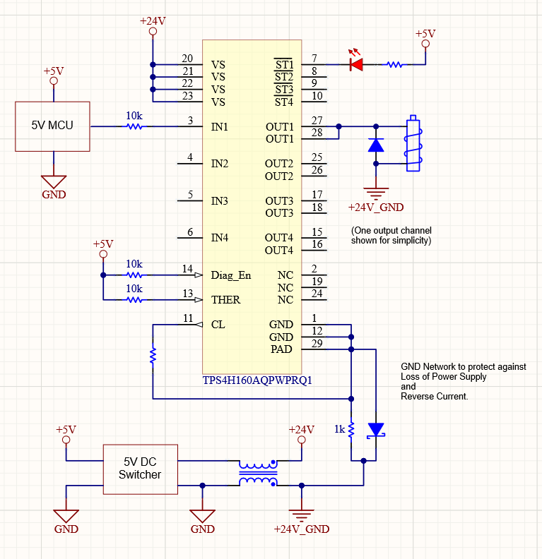
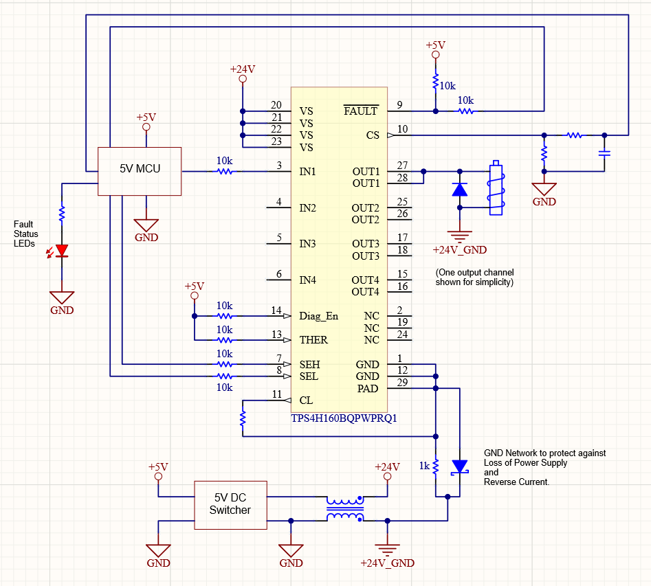
Here is a simplified schematic showing the circuit with the grounds and supplies.  I've shown example circuits for both the A and B versions of the TPS4H160.

In particular, please consider the following questions:

1. Since the frequency of switching is very low, will the TPS4H160 behave properly given the ground differences I've outlined?  The rising edge of the control input is an AC waveform, but only for the duration of the leading and trailing edges.  The circuit should stabilize before the next edge occurs.  Will the inductance of the choke cause problems with overshoot and undershoot?  If so, can this be mitigated by slowing down the edges, or are there components I can add to clamp them?

2. Are there any issues with +5V and its ground supplying DIAG_EN, THER, SEH/SEL, or the fault LEDs?

3. The B version has the additional issue of the MCU accurately measuring the Current Sense (CS pin) output.  Is the CS output a current source?  If so, would it be permissible to connect that output to the MCU's ground?  If it is truly a current source, wouldn't the voltage dropped across the resistor be accurate even though the grounds are dissimilar?  But since the grounds are connected to each other via a 470 uH inductor, I assume the frequency response would be affected and the inductance could affect the current source circuit.

If this is a dicey configuration, I won't do it and I will need to isolate the circuit.  Or I could use a much beefier common mode choke and supply the TPS4H160 drivers with filtered 24V.

Thank you very much for the help.

Regards,

Greg

  • Greg,

    Could you elaborate on what exactly the 5V DC Switcher is and what its function is here?

    Generally we discourage having separate ground planes as they tend to be a bit unpredictable and would not represent a use case that we have tested or validated with the device's use case. It's an interesting approach, however I would say the safe approach here would be to isolate your circuit. 

    The 5V into the control pins generally will not be an issue. The pins are rated for an absolute max of 7V. If there is anything weird going on with the ground pins though that would cause the potential to rise above the absolute max relatively it would cause problems. 

    The CS pin is a current source. Essentially what happens is there is a current mirror inside the device that scales down the output current and outputs it to the CS pin. That current is run over an external resistor to convert it to a voltage and then the MCU's ADC is able to sample it to determine what the output current of the device is (see https://www.ti.com/lit/an/slvae08/slvae08.pdf?ts=1588020757581 for a bunch of detail on the inner workings). The inductively connected grounds here will cause some uncertainty with this pin though as any slight current variation on that pin will cause an inaccurate current reading (we are talking about mA coming out of the pin).

    Will it work? Maybe- however I can't really guarantee it. Probably not the answer you were looking for but the safer and more robust solution here would be to isolate your circuit.

  • Hi Timothy,

    I included the 5V switcher in the schematic to show how the MCU was powered.

    Yeah, it wasn't the answer I was hoping for, but I thought I might as well ask just in case it was possible.  I can see the possibility of inductive bounce causing a difference between the two grounds that could be destructive to those inputs.

    Thanks for the link to the app report on current sense in high-side switches.  I'm sure I'll enjoy reading it.

    Thank you for the help.

    Regards,

    Greg