This thread has been locked.

If you have a related question, please click the "Ask a related question" button in the top right corner. The newly created question will be automatically linked to this question.

TPS2595: TPS259573 PSPice simulation: Unclear result of the fault output

Part Number: TPS2595

Hello,

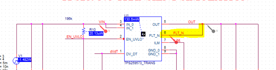
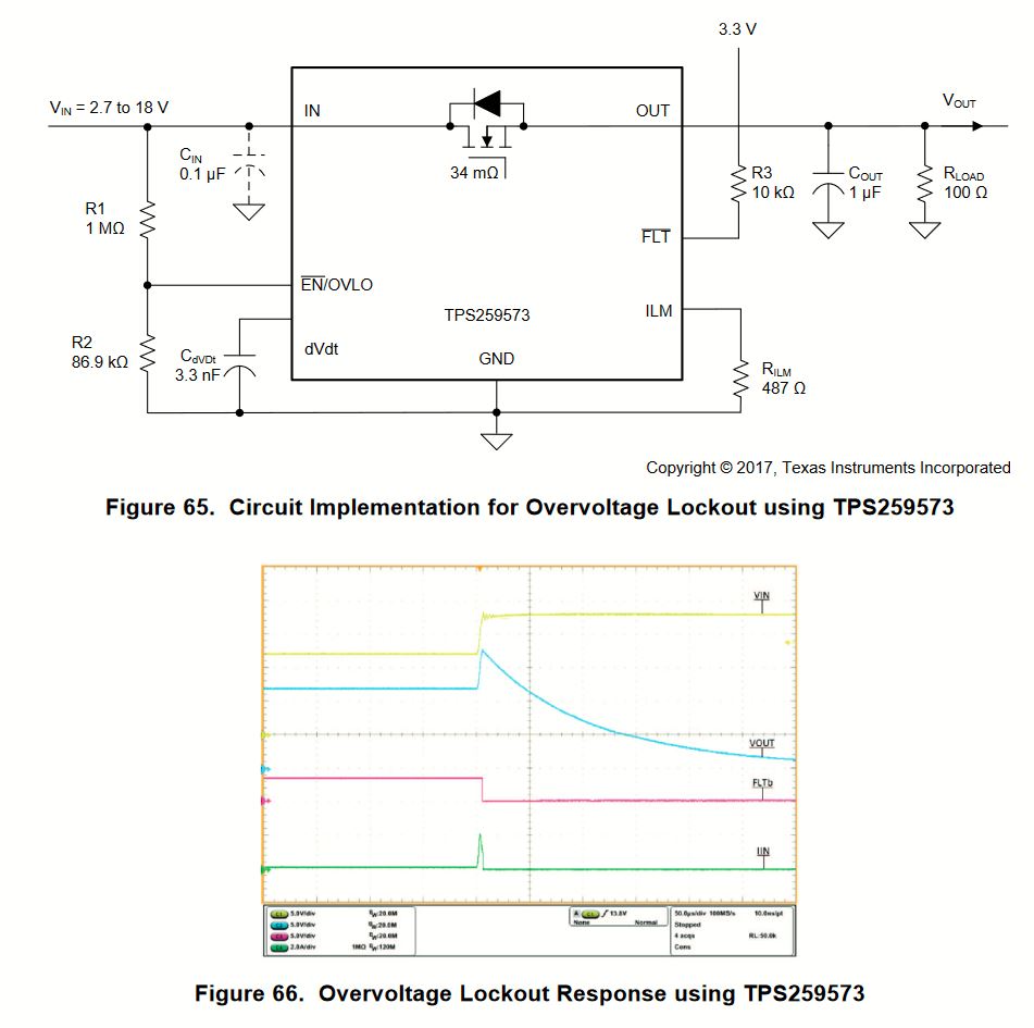
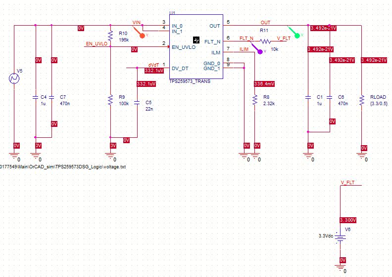
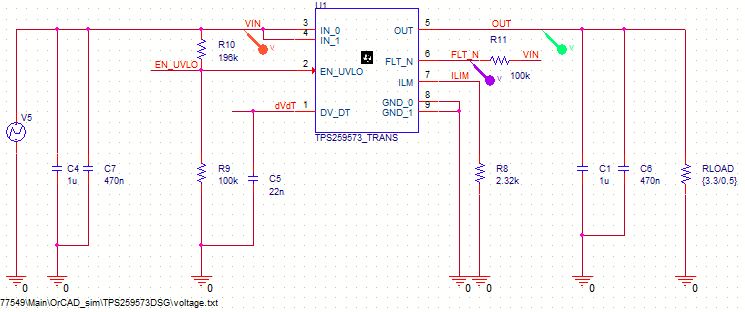
on the TPS259573 the fault output should respond when an OVP occurs. In the simulation this output is constant on a LOW level after a short peak.

I do not understand this behaviour and need some help.

Simulation:

I hope this time the images are uploaded!

  • Hi ,


    Looks like the images have not been uploaded properly. Can you upload them once again ?

  • Hi Yildirim,

    I can view the images now. I will check this simulation and get back to you with my observations in couple of days.

    If possible, can you share your simulation file here ?

  • Hey Praveen,

    I have attached the simulation as a zip file.

    Best regards,

    Kübra Yildirim

    TPS259573DSG_logic.zip

  • Hi Yildirim,

    Thanks for sharing the simulation file.

    FLT/ is an active low signal and asserts LOW whenever there is a fault in the system. TPS2595 asserts fault whenever the internal FET is turned OFF.

    In the simulation to get the actual behavior of the FLT/ signal , tie the FLT/ signal to the OUT pin as shown below.

    Practically on your system, you can tie FLT/ to any external voltage as long as it is <= Recommended Operating Voltage of FLT/ pin.

  • Hello Praveen,

    thanks for your answer. With this circuit I achieve that the FLT_N voltage is equal to the Out voltage. But I would like to use this FLT/ as an output for monitoring. I was just surprised that this FLT/ does not react even if I connect a constant external voltage and the device detects an overvoltage.
    In the datasheet there is an example for an overvoltage lockout. The FLT/ pin becomes LOW only when overvoltage is detected.


    If I reproduce this in the simulation with an external source, it does not react like in the datasheet. Or am I wrong?
    What could be the reason for this?

    Best regards,

    Kübra Yildirim

  • Hi Kübra Yildirim,

    Your observation is correct. The FLT/ pin in the model operate correctly/as expected only when it is tied to the OUT pin. This seems to be  problem with the model and we will rectify this in our next revision.

    The waveforms you see in the datasheet and your understanding on how it works is correct.