This thread has been locked.

If you have a related question, please click the "Ask a related question" button in the top right corner. The newly created question will be automatically linked to this question.

TPS65218D0: PMIC shuts down immediately after starting (and then restarts)

Part Number: TPS65218D0
Other Parts Discussed in Thread: AM3358, , TPS65218, TPS51200

We have an TPS65218D0 connected to an AM3358. The board also has some Cyclone 10 FPGAs connected to other PM parts.

The FPGA I/O (+3.3V) is generated from a LM20143MHE.
The PGOOD signal from that part enables the TPS65218 using pin 46 PWR_EN.
There is thus a power sequence where the FPGA I/O is turned on first.

We have 10 boards. It fails on 9 of them when +3.3V is to turned-on.
The last board we could get to work after changing power supply.
We find that the board draws 0,6A from the 5V.
We have tried with four different power supply on the other boards, but they do not start properly.
We do not use DCDC5 & 6 or GPIO1

We see around 2.2V on the DCDC4, and we suspect that the FPGA I/Os drive the CPU I/Os

It is 3.3-2.2 = 1.1 or almost twopdiode drops.
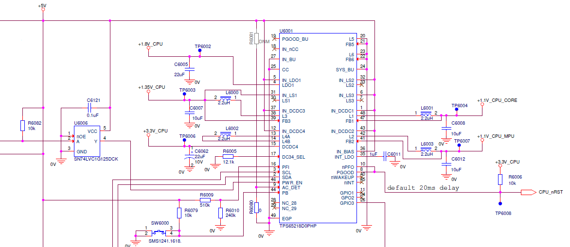
Schematics below.

The Cap is 22uF, based on http://e2e.ti.com/support/power-management/f/196/t/844935

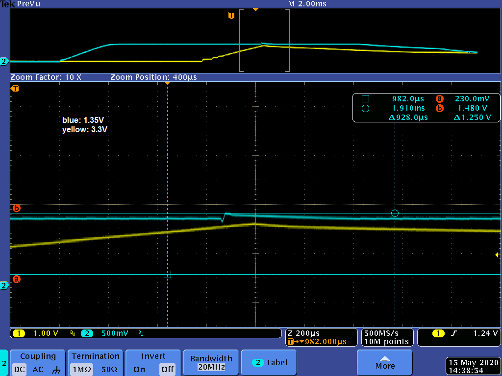
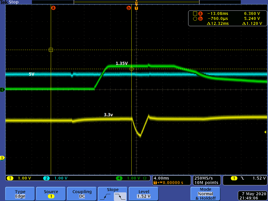
The 1.8V turns on first. There is a  minimal dip in the 5V supply when that happens.

Then 1.35V turns on after that. This seems also to work, reaching its voltage in 2 ms.

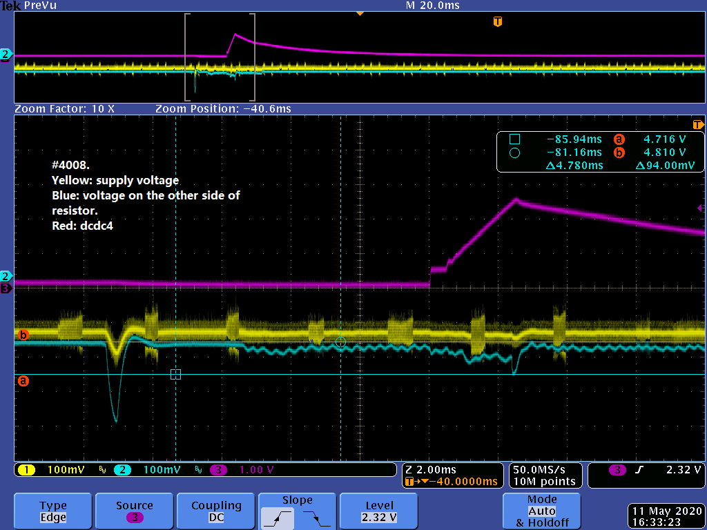
The 3.3V has ~2.2V value, then starts to *drop* 0.6V,  5 ms after the +1.35V reaches its value, and then starts to increase again
and then shuts off.

We would like to understand the power sequence timing better.

The sequence should be ..., DCDC3=1.35V, GPIO1, DCDC4=+3.3V, ...

DCDC4 (+3.3V) should start DLY5 + DLY6 after DCDC3 (+1.35V)

DLY5 = DLY6 = 2 ms, so DCDC4 should start 4 ms after DCDC3.
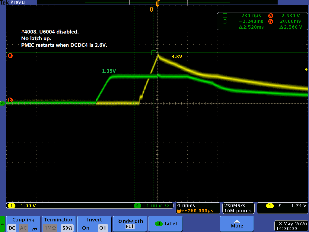
In the picture below we see that DCDC4 gets a dip after 7/5*4 ms or 5,6 ms, and then rises to 2.6V until 10/5*4 ms = 8 ms.
This is 2,4 ms after it starts which is before the 5 ms time alloted before it should shut itself down.

To avoid the interference from the FPGA we shut down the regulator to get this picture.

The +3.3V regulator turns on 7/5*4 ms after the 1.35V, (5,6 ms).

It still shuts down at 10/5 * 4 ms or 8 ms after +1.35V and has reached 2.6V at that time.

We have 15 I/O pins which are pulled up to DCDC4 using 10k ohm resistors.
An LED is connected with a 330 ohm series resistor, but this is normally off in this state.
There is about 60uF of decoupling caps. Most around the CPU (5 x 10uF)
Vcc for

  4 x single gate
  1 x SPI flash
  1 x NAND flash
  1 x clock buffer
  1 x TPS51200BCT for DDR3 voltage
  1 x TMUX1574PW analog mux.
  2 x SDRA05-4R2 USB protection circuits.

Does not seem to be something that would overload the DCDC4.

Any ideas?

  • Ulf,

    Thank you for providing so many details and oscilloscope captures. I will review the material and provide my hypothesis about the root cause of the problem, but it may take 1-2 days for me to review & respond.

  • Ulf,

    The schematic did not attach correctly. Could you please try to attach again?

    Ulf Samuelsson said:
    The Cap is 22uF

    Which cap is 22uF?

    Also, what is the full orderable part number of the TPS65218D0 IC? Is it TPS65218D0RSL (QFN package) or TPS65218D0PHP (SOIC package)? 

    Assuming you are using the PHP package version, what is the top-side marking on the IC? Do all the ICs on failing boards have the same top-side marking?

    Ulf Samuelsson said:
    We have 10 boards. It fails on 9 of them when +3.3V is to turned-on.

    On the 1 board that was working correctly, is the top-side marking different than the other 9 ICs?

    I may have more follow-up questions after I get a chance to review the schematic.

  • Hi Brian

    Here is the PMIC schematic. All DCDC input of PMIC has capacitors near by, they are not placed on the same page therefore not visible in the schematic below. The 22uF Ulf has mentioned is C6062 on the output of DCDC4. 

    The part number is TPS65218PHP(SOIC) package. Both good board and failing boards are marked T65218D0 96WG4 ATV9 on top.

    We have also checked current consumption when DCDC4 starts and restarts, by connecting a 0.57ohm resistor between board and power supply. The current increase when DCDC4 triggers the restart is quite small. So it doesn't look like there is any short circuit on the DCDC4 power domain.

    BR/Ying

  • Ying,

    Can you confirm the Thermal Pad is correctly soldered to GND?

    The landing pattern for the Thermal Pad should have an array of Vias that connect directly to the GND plane on an inner layer.

    There are no dedicated GND pins on the TPS65218D0 device, and for some reason it is more common for people to make the mistake of not connecting Thermal Pad to GND when using the PHP package of the device.

  • Hi Brian

    I have checked that the Thermal Pad is connected to GND.

    BR/Ying

  • Hi Brian

    I have been thinking that DCDC4 is the problem.  But 1.35V looks a bit suspicious before 3.3V goes down. It goes up to 1.48V.

    Is there any monitoring circuit on the status of DCDC3? Could it be this spike that triggers the restart?

    BR/Ying

  • Ying,

    WOW! This is a very helpful piece of information.

    For the TPS65218D0, the STRICT bit is set to 1b. If you look at the datasheet, it tells you that DCDC3 will experience an over-voltage fault (VOV) when VDCDC3 > 104% (1.35V*1.04 = 1.404V) for more than 50us.

    I believe your theory is correct. The oscilloscope capture you shared clearly shows VDCDC3 = 1.48V which looks like it lasts for longer than 50us. This would be a VOV fault and would cause the PMIC to stop the power-up sequence and shutdown.

    Now, we just need to find out where that spike is coming from and we will know the root cause.

    • Does it happen at the same time as when DCDC1 or DCDC2 turns on?
    • If so, is it possible DCDC1/2 and DCDC3 are coupled together in the layout of the PCB?
    • Is there an external noise source that is coupled onto the DCDC3 feedback signal?

    Obviously, I do not know the answers to these questions yet, but I think we are finally on the right track to solving this problem.

  • The +3.3V_CPU is used to enable a TPS51200 providing the Vref for the DDR3 memory. It turns on when the +3.3V_CPU reaches about 2,6V.
    Talked to Ying, and she had noticed that the C200, C201 caps are ~2 cm away from U41, they should perhaps be closer.
    We found one 10uF cap between +1.35V_CPU and GND closer to U41, and we will try increasing the value.
    Even worse, the C6007 which is part of the LC of the DCDC3 (see previous schematics) is not close to the PMIC. It is at least a couple of centimeters away.

  • My guess what happens is that the U41 starts to draw current, causing the initial dip in the 1.35V, and then the PMIC reacts to the dip
    starting to pump current, causing the overvoltage condition.

    What would be the best way to fix the current boards.

    • Change value of the DCDC3 LC components (L6000, C6007)
    • Change values of the C200,C201?
    • We have 10V caps. Can changing the type of caps affect the situation?

  • From my side, if you make the initial "voltage dip" smaller and the recovery voltage hump smaller, then the issue would be resolved.

    In other words, increasing the capacitance of C6007, C200, and C201 would all be helpful.

    Changing from 10uF to 22uF would be nice, but not always possible due to package size. It is easy to find 10uF in 0603 package, but not easy to find 22uF smaller than 0805. Using a capacitor with a higher voltage rating would be good (10V to 16V, for example), or changing the type of capacitor might help (using X7R is best and X5R is OK but using Y5V is never advisable, see this link). Any one of these changes would increase the effective capacitance on the DCDC3 output path.

    While you are simply debugging a board, you can also stack multiple caps on top of the existing component to test your theory. This is quick and relatively easy to do with hand-soldering, as opposed to fitting an 0805 package on 0603-sized pads.

  • We added some more capacitors, but it did not help, the voltage bump was reduced to 1.47V instead of 1.48V.

    We are thinking to use the TPS51200 Enable signal instead.

    This is currently pulled up to +3.3V_CPU by 10kOhm resistor (R1124).

    When the +3.3V_CPU reaches 2.6V this will turn on the EN pin.

    We decided to remove the resistor and now it is controlled by an I/O pin.

    Currently this means that the pin is floating, because the CPU pin used is defined as an input during reset.

    Reset is directly connected to PGOOD of the TPS65218.

    Once all the power rails are stable and PGOOD goes high, this pin has a pulldown.

    The PMIC starts properly after this modification on a test board.

    We see two options.

    1. Ideally, when the rest of the power structure is stable, we do not see the bump going over the limit, so PMIC does not turn off.
    2. If it still happens, Ying came up with the idea to disable the PMIC max voltage check temporarily using the I2C interface,
      and then turn on the EN pin. The PMIC max voltage check is restored soon after the bump has receded.

    What do you think of this idea?

  • I do not know where the DDR3_VTT_EN signal originates from, but I would prefer that this signal has a pull-down to GND by default instead of a pull-up. If the pin on the CPU can be configured as push-pull instead of open-drain, this would be ideal.

    Otherwise, it is OK to set STRICT=0b for all time to disable VOV (over-voltage) faults. The STRICT=1b conditions were initially created for AM438x systems that require additional security for protecting EPOS systems from tampering. No need to set the bit back to 1b at a later time.

  • The DDR3_VTT_EN is the AM335x  LCD_AC_BIAS_EN pin which is an input (no pull) on RESET (PMIC PGOOD signal), but as soon as the RESET is deasserted, the pin has a pull-down.

    It will take a few milliseconds before the +1.35V_CPU is powered up, so it should disable the EN pin in our first prototypes before that. The pulldown has to come in the next revision.

    Some simple tests show that the PMIC starts when the resistor is removed, but we have to check what happens when DDR3_VTT_EN is asserted.