This thread has been locked.

If you have a related question, please click the "Ask a related question" button in the top right corner. The newly created question will be automatically linked to this question.

UCC28070EVM: Test loop current gain and phase

Part Number: UCC28070EVM
Other Parts Discussed in Thread: UCC28070

HI sir 

I test Figure 6. Current Loop Gain (TdB (f)) and Figure 7. Current Loop Phase (qc (f)) in SLUA479A

The Schematic(page 2) in SLUA479A 

I actually tested it and have some question , please refer to the attachment for the results

3107.UCC28070EVM current loop gain and phase measurement.docx2311.UCC28070 Design Review 300W Interleaved PFC- slua479.pdf
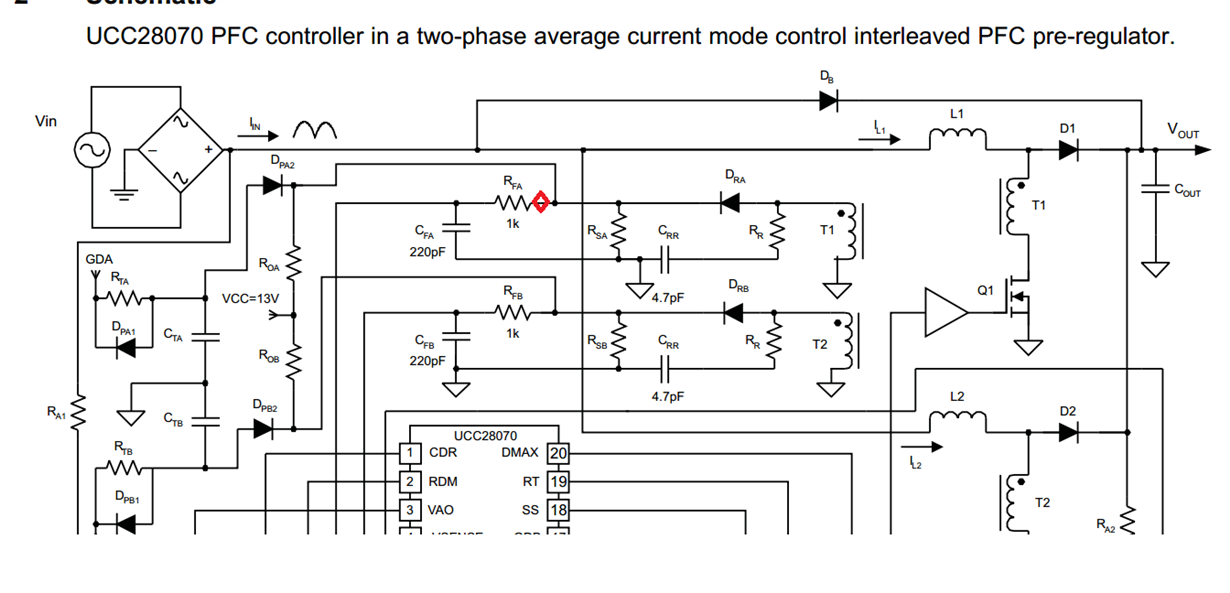
  • Hello

    I think the problem is that the UCC28070 uses Average Current Mode (ACM) control rather than Peak Current Mode (PCM) control. The injection point you chose would be correct for a PCM controller because the perturbation you inject across the 10 Ohm resistor affects the entire signal being used by the current loop. The problem is that in the ACM system used by the UCC28070 a perturbation to the CSA signal affects only part of the signal being used by the current loop. The injected signal affects the CSA signal but does not affect the synthesised downslope part of the signal. I've looked at your schematic and at the controller block diagrams and I don't see a suitable injection point where the full average current signal could be perturbed.

    I think this is the main reason you are seeing different results to those in the App note. A second reason may be that there is some interaction between PhaseA and PhaseB of the PFC stage. Please note too that the graphs in Fig 6 and 7 of the app note are calculated not measured.

    If you want to look at the current loop stability then I'd suggest a load transient test - you can set up the PFC stage to run from a DC source as before and apply a rapid change to the load - typically a 50% to 100% load step applied as fast as possible. This means that the step must happen faster than the loop bandwidth - if you assume a 20kHz bandwidth then the step should happen within 20us or so - a MOSFET and resistor can be used for this if the Electronic load is too slow.

    You should probably disable one of the interleaved stages so that there is no interaction between their two loops.

    Please let me know if you need any further help.

    Regards

    Colin