This thread has been locked.

If you have a related question, please click the "Ask a related question" button in the top right corner. The newly created question will be automatically linked to this question.

TPS3780: TPS3780B: discrepancy in the truth table and the behavior of the IC

Part Number: TPS3780

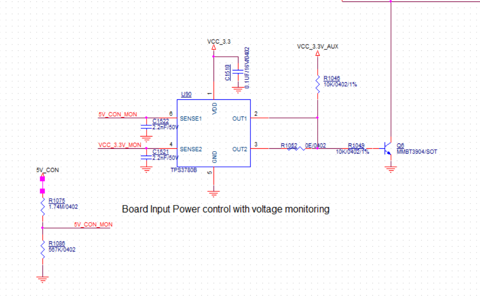
 In a design of ours we have used TPS3780B, to monitor 5V and have found discrepancy in the truth table and the behavior of the IC. 


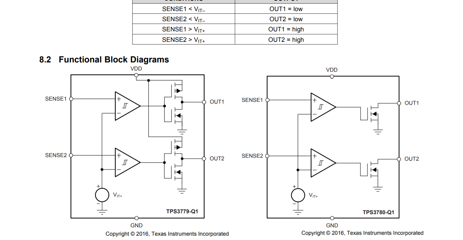
If SENSE1 is greater than the threshold VIT=1.194V, OUT1 = LOW, since output of comparator is high, NMOS will be on, resulting in OUT1 to be logic low.

In my design i have used 

R1=1.74MΩ and R2=567KΩ so my SENSE1 would be 1.22, greater than 1.194 and OUT1 = LOW

Tried with other values and increased SENSE1 upto 1.8V still OUT1=LOW was the scenario.To see the working when SENSE1<VIT, I have used R1=10MΩ and R2=1MΩ, SENSE1=0.45V, at this condition OUT1 was High.


Please kindly look into the functionality at your end.

  • Hi Akshat,

    Let me ask one of our product experts on this part to help you out with this.

    Thanks,
    Abhinav.

  • I have checked in another design which was the parent design and was working fine. It was because SENSE1 level was 1.18V. But practically speaking it is not considering 5V to stabilize and powering on the board right on. I had to use a inverter to correct the logic. 

  • Kiranmayi,

    The truth table is correct and accurately reflects the behavior of the device. When SENSE1 or SENSE2 are below VIT-, the corresponding OUT will be logic low. When SENSE1 or SENSE2 is above VIT+, the corresponding OUT will be logic high. The block diagram is useful to show the output topology but please rely on the truth table and description to determine how the device behaves.

    The VIT- values at SENSE1 and SENSE2 are fixed. You can adjust the values that cause a fault using a resistor divider. The voltage at VMON determines the voltage seen at SENSE and the OUT logic depends if the SENSE voltage is above or below VIT-

    Please provide a schematic and scope captures if you are still having issues.

  • Hi Michael

       I am attaching the schematic. As you told the truth table was matching with below mentioned change.

    I resolved the issue by changing the pull up voltage to  5V from 3.3 Aux.

    But why is it like when OUT1 is pulled up to 3.3 Aux supply it acts as an inverter and corrected when replaced with 5V?

    Regards

    Kiranmayi 

  • Is it possible that when using the 3.3 Aux supply that the device is triggering a reset, but not when the device is using the 5V supply? I check the rising threshold for this device variant and is it 1.194 V +/- 1% so ~1.2V and the calculated threshold with 5V for R1075 and R1086 is 1.229V so there is very little margin and not accounting for resistor tolerance. I think the device is working as expected but the tolerance due to supply accuracy, resistor accuracy, can be causing false resets.