This thread has been locked.

If you have a related question, please click the "Ask a related question" button in the top right corner. The newly created question will be automatically linked to this question.

TPS55340: An output voltage overshoot with TPS55340 at no load condition.

Part Number: TPS55340
Other Parts Discussed in Thread: TPS61175, LM5121

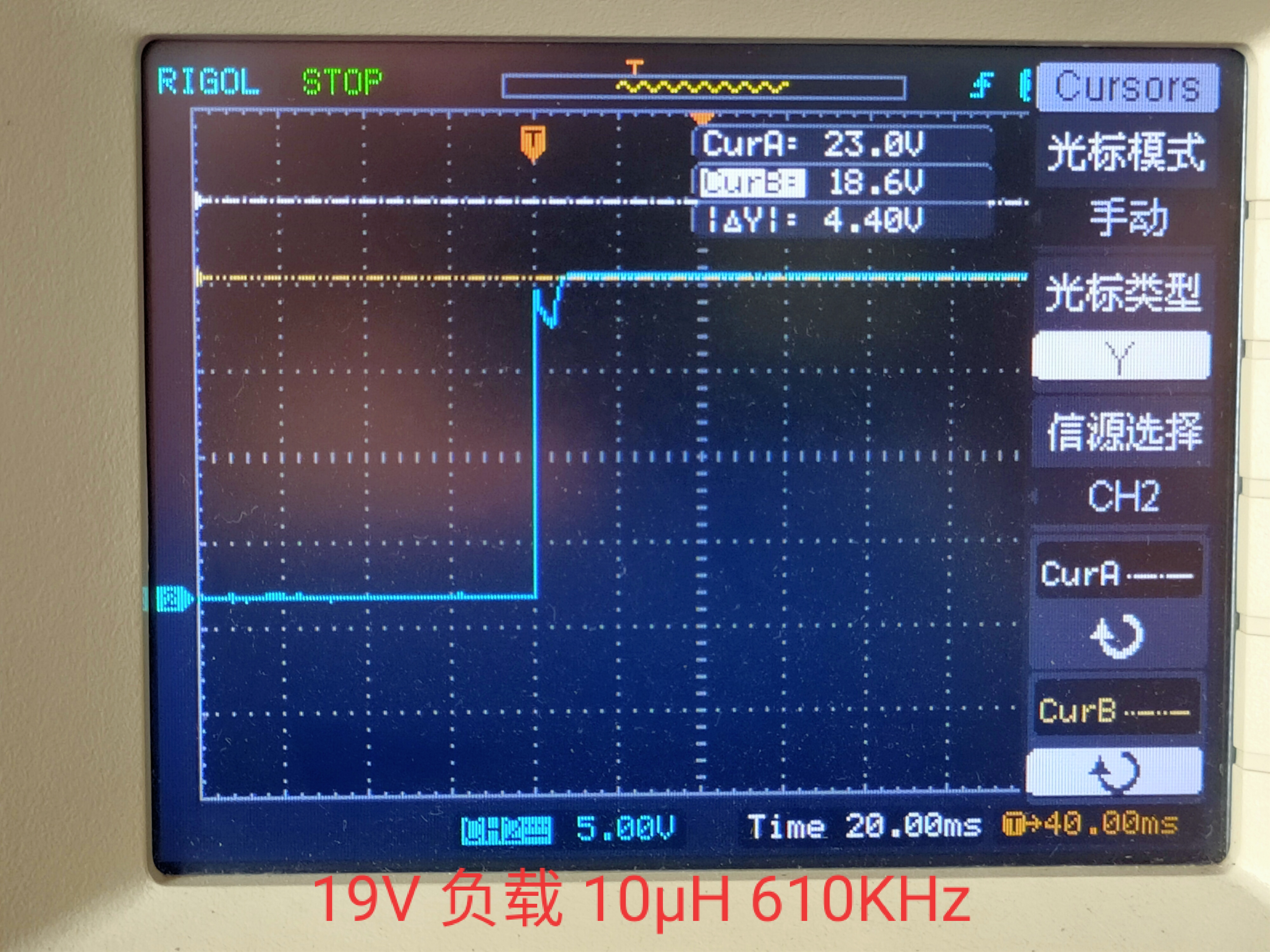
1. When I use TPS55340 or TPS61175, (12V->19V),  an output voltage overshoot  at no load condition.

2.Changing the inductor to a smaller one(22uH -> 6.8uH). this removes the overshoot .

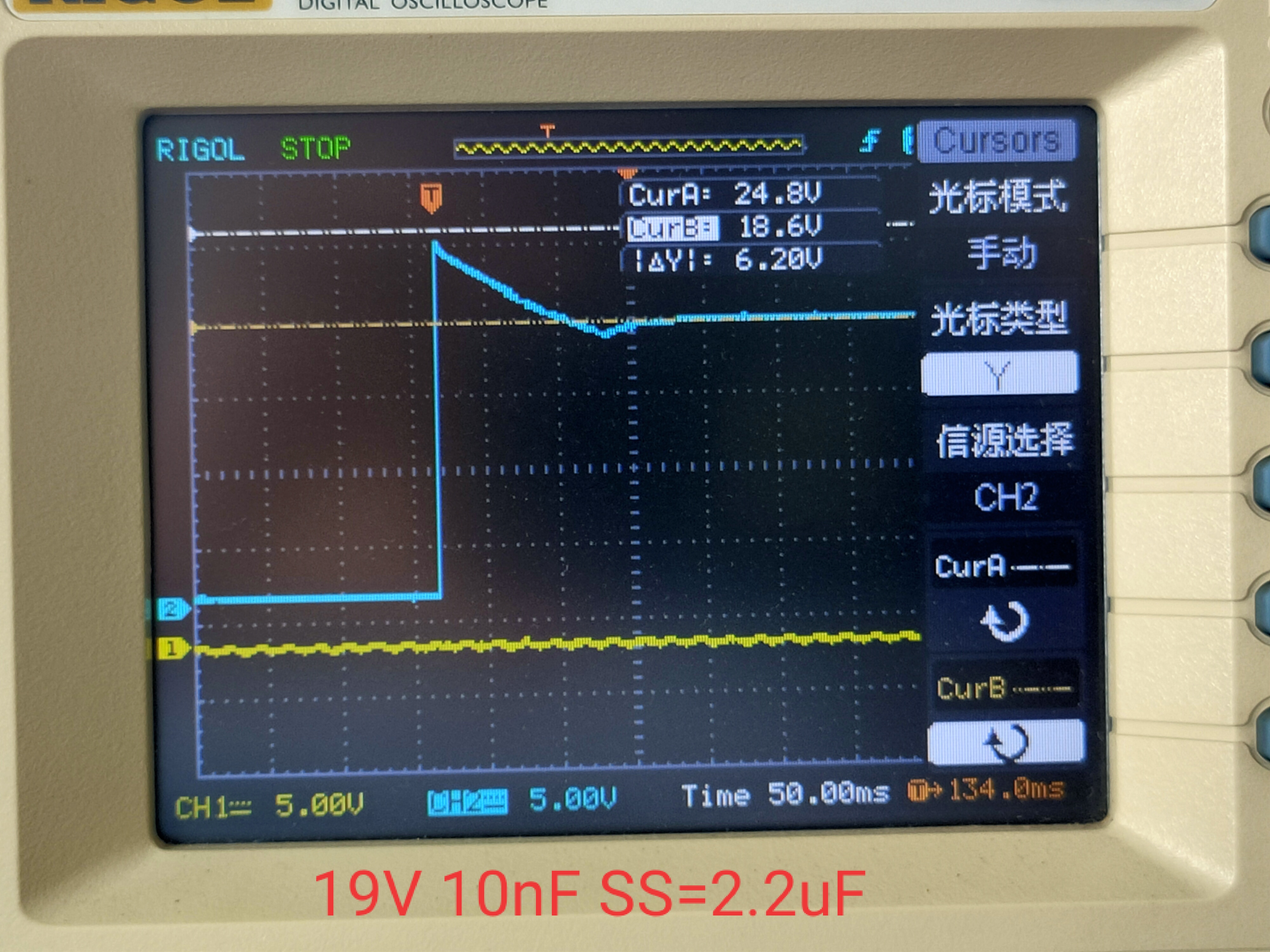
3. Changing CSS can't eliminate overshoot,I feel that the soft start has no effect

How to eliminate overshoot?

  • Hi User,

    Thank you for using our products.    Soft start capacitor should help reduce the overshoot. Overshoot is also the results of slow loop response.   Could you share your schematic?

    Thanks,

    Youhao Xi, Applications Engineering

  • Hi, Youhao Xi

    Schematic

    Soft start capacitor Css=2.2uF,  COMP capacitor C46=10nF, R29=2K,  No load

    Soft start capacitor Css=2.2uF,  COMP capacitor C46=10nF, R29=2K,  load

  • Hi User,

    Thank you for the schematic.  It seems the Soft-start is hidden by the overshoot of the output.  The overshoot is seemingly caused by the LC resonance when you apply the input voltage.   In the second scope picture, the relatively slow ramp up of VOUT after the overshoot (at about 100ms) is the evidence of the soft-start behavior. 

    The boost circuit has a natural, uninterrupted current path from the input to the output:  VIN-->Inductor-->Diode--VOUT, and there is no mechanism to stop this path.  The inductor and the output capacitor form the LC tank. During power on, you basically create a transient in an LC circuit, and the output voltage can overshoot.  

    Three options to reduce the overshoot at input voltage application:

    • Slow down the input voltage application slew rate,
    • Add an inrush current limiter at the input, you you can consider a device like the LM5121 to limit the inrush current.
    • Insert a NFET between the output capacitor negative lead and the ground, and use an RC delay to turn ON the NFET or BJT slowly to limit the inrush current and hence overshoot.

    Best Regards,

    Youhao Xi, Applications Engineering

  • 1. Remove the resistance connecting en and VIN, and there is still overshoot, which should be caused by LC.
    2. If a 22uF ceramic capacitor is replaced by a 10uF or 100uF tantalum capacitor, there will be no overshoot

  • You are right:  you will have much lower Q-factor with the tantalum capacitor due to the damping factor provided by the ESR, but this may lead to higher ripple voltage during operation.  You may consider to parallel ceramic with a tantalum to have both the low ripple and also to prevent LC resonance. 

    Thanks,

    Youhao

  • May I assume this issue is resolved so I can close the thread here?  You are welcome to re-open the thread  by adding a new post. 

    Thanks,

    Youhao