This thread has been locked.

If you have a related question, please click the "Ask a related question" button in the top right corner. The newly created question will be automatically linked to this question.

TPS54331: TPS54331 Input: 4.5 - 9V Output:3.5V

Part Number: TPS54331
Other Parts Discussed in Thread: TPS54302, TPS563201, TPS56339

Hello

I have a question concerning the technical specification of TPS54331.

I habe an circuit where the Input Voltage is: 4.5 to 9V and the output voltage is 3.5V.

Maximum current 2.2A

In the datasheet there is an example circuit:

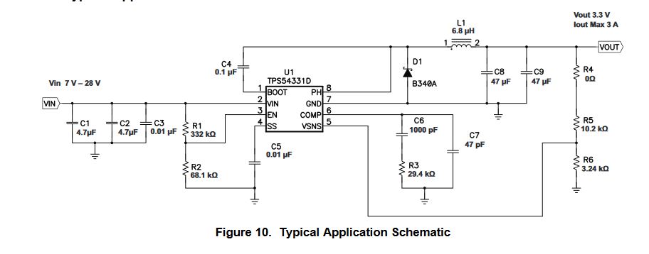
V_in is limitted from 7-28V. Why is this the case.What happens if the input voltage goes down to 4.5? What do I have to change for Input 4.5 to 9 when output should be 3.5?

What limitates my input voltage?

Best regards

  • Former Member
    0 Former Member

    Hi Fabian, 

     TPS54331 is a non-synchronous buck converter, and the high-side MOSFET is N-channel MOSFET.

    To drive this HS MOSFET properly, a bootstrap circuit is designed to generate a floating power supply between gate node and source node of the MOSFET and an external small ceramic capacitor between the BOOT and PH pins is required. This bootstrap capacitor is refreshed when the HS MOSFET is off and the catch diode or low-side (LS) MOSFET conducts. An undervoltage lock-out (UVLO) circuit is also required for the gate drive supply to keep the converter from attempting to switch when the gate drive may be too low(BOOT-PH<2.1V).

    It means that in non-synchronous buck converter (TPS54331) when the targeted Vout is close to Vin, the BOOT-PH (gate drive) voltage is lower than 2.1V, then HS and LS MOSFET will be turned off, leading unstable and not correct output.

    There are several solutions for the low drop-out operation. Please check the app note for detailed explanation :

    https://www.ti.com/lit/an/slua928a/slua928a.pdf?ts=1590664402104

    Thanks.

    Bruce

  • Thanks Bruce, would the Synchronous TPS54302 be a better choice for the application?

  • Former Member
    0 Former Member in reply to Fabian Hoppe

    Hi Fabian,

    Yes,TPS54302(28V/3A) and TPS56339(24V/3A) and TPS563201(17V/3A)are better choices for this application.

    I would like to recommend using Webench tool to accelerate your design process.

    https://webench.ti.com/power-designer/switching-regulator

    BRs,

    Bruce

  • Thanks, the webench tool seems to be great. TPS563201 has to much quiescent current in shutdown mode. 1-2 uA would be the aim. Is there also an possibility to filter quiescent current in webench tool? Furthermore there are sometimes small peaks in power consumption (2A) which should be possible to handle by the voltage regulator.

  • Hi Fabian,

    The WEBENCH tool can't support the quiescent current modeling so far. Quiescent current in shutdown mode is different from in non-switching mode or normal switching mode. If you want the device to be always working, then you don't need care about the quiescent current in shutdown mode. Selecting a lower quiescent current in non-switching mode would help to reduce the power consumption.

  • OK, thanks for your answer. I have an last question concerning the datasheet of the TPS54302. Why is there in the reference circuit an R1 ?

    When I use WEBENCH I can't find R1.

  • Hi Fabian,

    The R1 is used for the bode plot test. It's not a must in your design. You can remove it.