This thread has been locked.

If you have a related question, please click the "Ask a related question" button in the top right corner. The newly created question will be automatically linked to this question.

BQ24780S: Test to damage input FET on purpose

Part Number: BQ24780S

Hi,

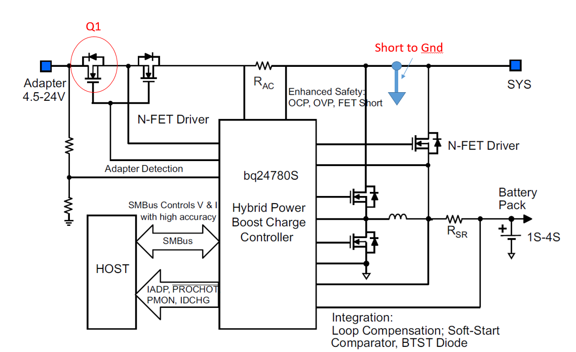
Now we need to test the robustness of the N-FET (Q1 as below), and tried to perform some stress (short-circuit) test it for it.  The test steps are,

  • Step1. Short SYS to GND.
  • Step2. Plug-in adapter

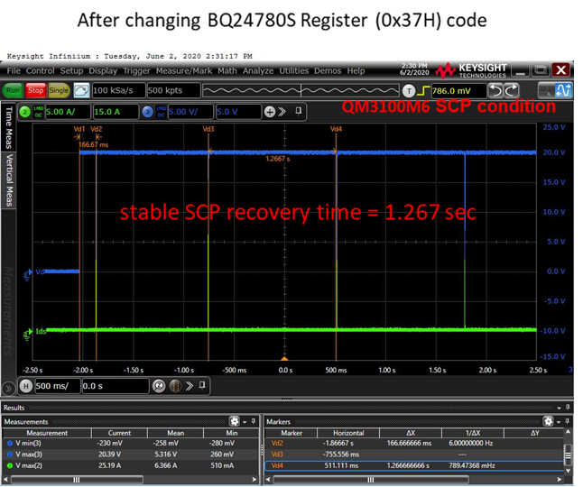
At this moment, we observe a 11~13A current spike lasting for ~1ms triggered periodically each 1.3 sec as below.

Since the 1.3sec internal is too long, the FET temperature is not rising high enough.  Is there any way we can shorten the interval of 1.3 second to around 150ms?  Or you have better suggestion to damage the FET on purpose?

We've tried to set 0x37[12] ( ACOK Deglitch Time for Primary Input (ACOK_DEG) ) to '0'  as shown below but seems no changes happen.  Please help us to clarify it.

Antony

  • Hi Anthony,

    With the 1.3 Second repeat, does it repeat 7 times and then latch off?  If so, then it is the 20 mSec gate drive turn-on requirement that is causing it to restart.  If this is the case, then the 1.3 Second repeat time is fixed.  If it is not latching off, then probably the adapter voltage is falling so that ACDET < 2.4V, but if this is the case, then the ACOK deglitch setting you referenced should have changed the interval to 150 mSec.

    I am glad to hear that it is so difficult to damage the ACFET!  If you need to purposefully damage it, then there are a couple of things you can try.  You can put a large capacitor (we have 100,000 uF in our lab) at the input so that the adapter input won't fall back below the ACDET < 2.4V threshold.  Also, you can adjust the C_GD and C_GS capacitors on the ACFET from 1 nF / 47 nF to 2.2 nF / 100 nF.  This will cause the input FETs to turn on half as fast, keeping them in the linear resistance range longer.  Usually a slower turn-on is more likely to damage the FETs.  The current spike won't be as high, but the added resistance and longer turn-on time will increase the power dropped across the FET.

    Regards,

    Steve 

  • Hi,

    We found it's not latching off after 7 times, and ACDET<2.4V.  After trying to configure ACOK deglitch time to 150ms (0x37[12]=0), the behavior seems not changed as below,  Do you have any idea why 150ms is not happening?

    Thanks!

    Antony

  • HI Steve,

    We add one mode signal (Vcc) measurement as below to make sure if the chip enters POR or not each time when we see a dip.  As shown below, Vcc would drop to around 5.3V, so the setting of 0x37[12] shall not set back to default value (1.3sec).  But we still don't know why the internal between two dips is still 1.3s even that we configure 0x37[12] to 150ms already.  Meanwhile, ACDET would drop to around 2.2x V in each dip.

    Another question is, 0x37[12] is used to define the deglitch time of ACOK.  I can't directly link this register definition to the behavior we see now (corresponding to the interval of two consecutive dips in this test.)  Is it some specific design not mentioned in datasheet?

    Thanks!

    Antony

  • Hi Anthony,

    Here is the result that I get on the EVM.  I ran two tests.  In the first, which I would call "weak adapter" I set 20V, 100 mA on power supply at the adapter and sink 200 mA on SYS with ELOAD.  This forces the adapter to drop below the ACDET 2.4V threshold and disconnect.  With the ACOK Deglitch Time (0x37[12]) set to 150 mSec, I get repeated attempts 150 mSec apart that will continue forever: 

    Then without changing the settings, I ran a second experiment where I shorted ACDRV to CMSRC.  This causes it to fail to turn on.  You can see that the first delay is 150 mSec, but after that each delay is 1.3 Sec.  It attempts to start 7 times and then latches off.

    Since your test case is not aligning to either of these two tests, I am a little confused.  Can you attempt to connect, verify that it tries at least 10 times without latching off, and then read the register settings after to verify that the REG0x37[12] is still set to 0b (150 mSec deglitch?)  The only thing that I can think of that would make it continue at 1.3 Sec intervals indefinitely would be if the REG0x37[12] is somehow getting reset.  I know you are capturing the VCC, but can you read the register value to verify?  Also, if you aren't running these tests with a battery, it might make sense to use a battery so that there is no chance of a power loss that will reset the register settings.

    Also, if you can zoom in on one of the attempts with a 4 mSec time scale, it may help us to see what is happening in the attempt that is causing it to abort.  If you can show ACDRV, CMSRC, VADPT, ACDET, we should be able to determine if it is disconnecting from ACDET or from failed turn on.  (Please align ACDRV and CMSRC with same offset so that it is easy to see the difference ACDRV-CMSRC and/or use scope math or a differential probe.)

    Regards,

    Steve

  • Hi Anthony,

    I haven't seen a response in about a week, so I am assuming that you were able to resolve this issue and am closing the case.  Feel free to re-open if you have further questions.

    Thanks,

    Steve