This thread has been locked.

If you have a related question, please click the "Ask a related question" button in the top right corner. The newly created question will be automatically linked to this question.

TPS23754EVM-383: The device cannot output 12V

Part Number: TPS23754EVM-383

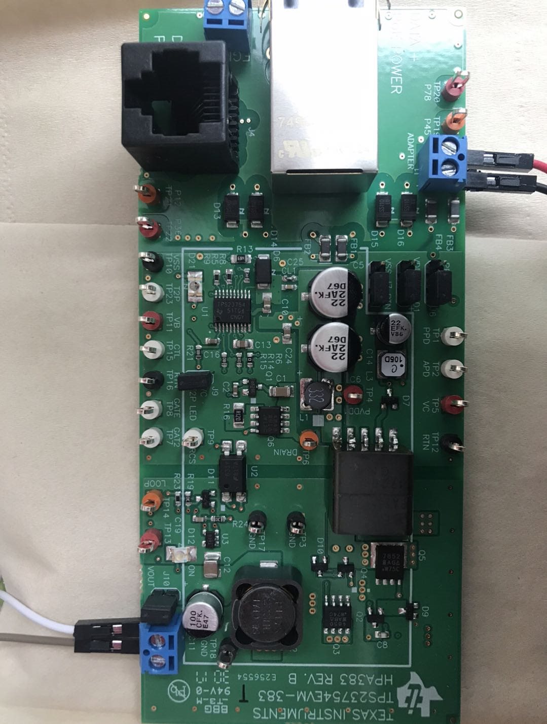
I didn't plug in a PSE, and only input 50V through the J1 plug(the adapter plug),and I've tried with and with a load through J2 plug(the OUTPUT plug),finally it could not output 12V at J2, it was 0V all the time. Is there any preset I missed or is there something wrong with the EVB? 

  • Hello Jane, 

    Can you confirm the position of the jumpers?

    Additionally, can you show the startup waveforms of VC, PVDD, GATE, and VB? This will help me understand if the IC is getting powered, and if so, is it damaged. Thank you!

    If this post answers your question, please indicate so by marking this thread as resolved. Thank you.


    Regards, 


    Michael P.

    Applications Engineer

    Texas Instruments 

  • Hi Michael:
    I've checked the jumpers,not connected well .Now the output of J2 plug(the VOUT plug) is 14V(the input is 50V). The output LED is lighted.
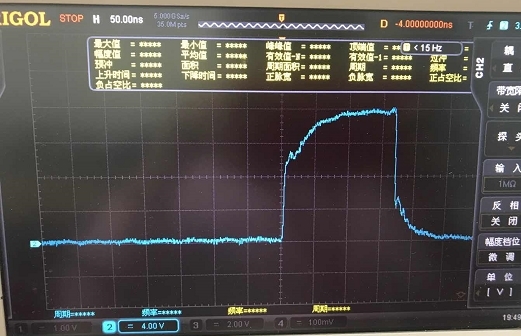
    The voltage on PVDD1 testpoint is 54V , the voltage on VC testpoint is 13V, and the voltage on VB is 5.8V. The startup waveform of GATE is shown belove:

    I wonder why the output voltage of VOUT(J2) is 14V instead of 12V?

    I am looking forward for your reply sincerely.

  • Hello Jane,

    I am glad to hear you are getting an output voltage now.

    Can you confirm again the jumper positions?

    Also, can you provide a waveform of Vout? I am curious to know if it is stable or if it is changing. 

    Lastly, what is the load on the EVM? Is is electronic or resistive?

    If this post answers your question, please indicate so by marking this thread as resolved. Thank you.


    Regards, 


    Michael P.

    Applications Engineer

    Texas Instruments 

  • Hi Micheal:

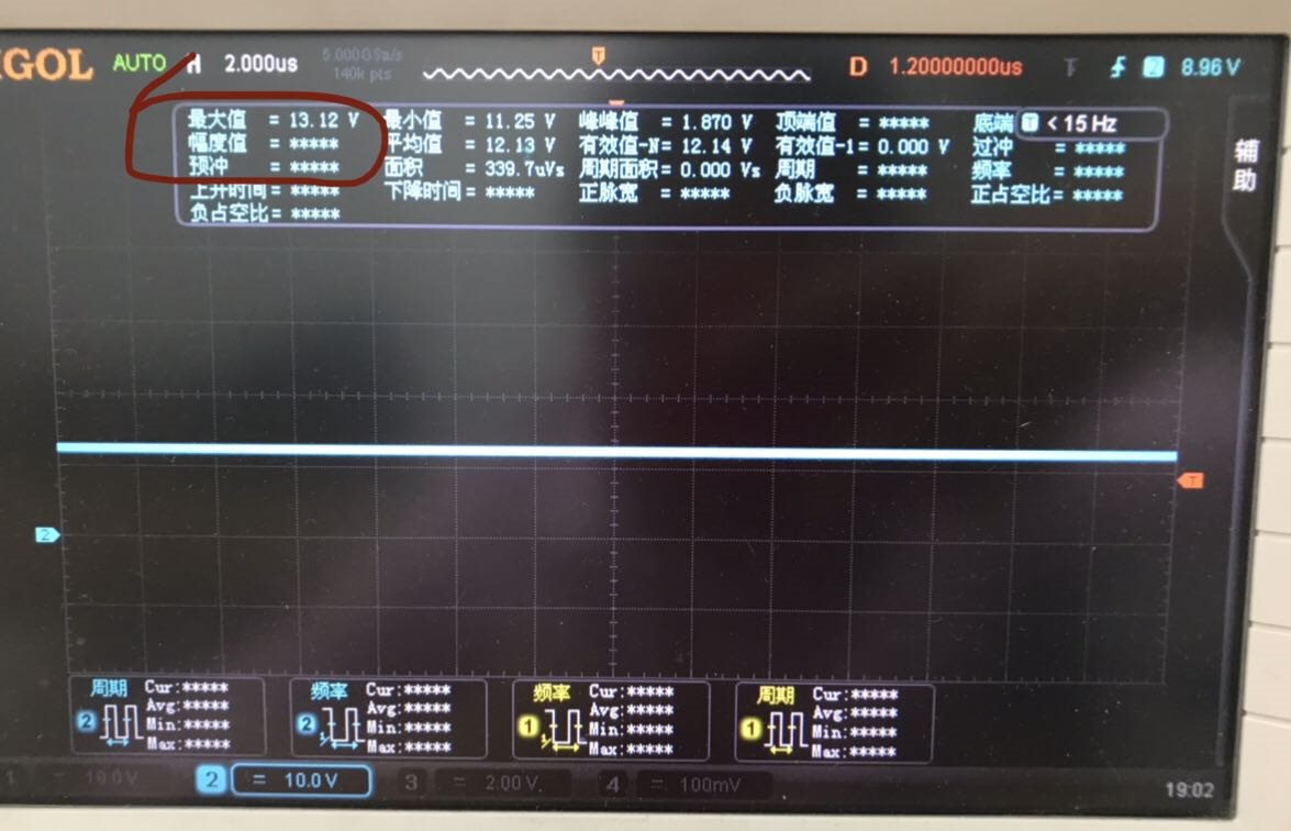
    The Vout changes slightly as the photo of it's waveform which is attached below , and the load of the EVM is resistive (10-25Ω).

    By the way, I'm not quite sure about the PPD and APD function. If I wanna monitor the type of the PSE device and keep the hotswap function actively, shoud I connect the PPD to the VDD and connect the APD to ARTN in my own design? Could you describe the process of the running option of PPD and APD and T2P which can implement these function above? 

    Thank you.

    BR,

    J

  • Hello Jane,

    What is the 12.13V and the 12.14V? Looking at the tick marks, I can see three tick marks above the voltage line, presumably indicating 14V, 16V, 18V, and then the next line being 20V. This would indicate the voltage is about 12V. 

    Can you try using a smaller volts/division to get a more accurate picture?

    As for APD and PPD, can you clarify what you mean? Are you saying you want to use an adapter voltage but keep the hotswap MOSFET on? What voltage is the adapter input? 

    APD is used to determine if an adapter voltage is present. 

    PPD allows a lower turn on voltage (usually 24V range).

    T2P indicates if a Type 2 PSE is present and up to 25W of power is available to the PD. 

    If this post answers your question, please indicate so by marking this thread as resolved. Thank you.


    Regards, 


    Michael P.

    Applications Engineer

    Texas Instruments 

  •  Hello,

    I have not heard from you in a few days. Do you have any update on this post? I want to make sure you are setup for success for your project, but if I do not hear from you I will close this thread. Feel free to post here or on a new E2E post to continue the conversation.

    If this post answers your question, please indicate so by marking this thread as resolved. Thank you.


    Regards, 


    Michael P.

    Applications Engineer

    Texas Instruments