Circuit specifications:
input voltage: 24 ~ 100V
Output voltage: 12V at 900mA ( Maximum load)
Power inductor: 100uH 2.5A 110mohms with 3A max saturation current.
PCB will be enclosed in IP65 enclosure at environmental temperatures > 40Degrees during daytime.
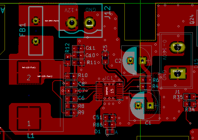
PCB circuit design based from schematic of evaluation module.
Test setup:
Input voltage: 75V
Output Voltage: 12V at 836mA load.
Switching frequency: 296Khz.
PCB Location: Not enclosed.
Room Temperature: 31Degrees Celcius.
Testing time: 10 ~ 15mins.

Test results:
1. No Load: We tested the setup with no load. Giving output of 12V steady with no heating issues.
2. When we put a load of 836mA incandescent lamp for testing purposes, the heating started gradually increasing over 10mins to given values on thermal image below. Maximum was recorded at 60Degrees Celcius heating surrounding areas of copper pour as well. Please check image below taken at LM5161 area in figure 1.
Figure1:

3. As temperature rises of LM5161, we noticed the heat also rises on 100uH inductor. Please check the figure 2 for thermal scan on Inductor.
Figure 2:

Questions:
1. Please let us know what may cause this heating issue since this board will be used fully enclosed IP65 box in a high environmental temperatures.
2. The conditions may worsen in that environment. We also want to know if we can provide additional heat sink to prevent this.
3. Also let us know if changing frequency will help improve the heat dissipation.
LM5161 - IC Heating issue
Circuit specifications:
input voltage: 24 ~ 100V
Output voltage: 12V at 900mA ( Maximum load)
Power inductor: 100uH 2.5A 110mohms with 3A max saturation current.
PCB will be enclosed in IP65 enclosure at environmental temperatures > 40Degrees during daytime.
PCB circuit design based from schematic of evaluation module.
Test setup:
Input voltage: 75V
Output Voltage: 12V at 836mA load.
Switching frequency: 296Khz.
PCB Location: Not enclosed.
Room Temperature: 31Degrees Celcius.
Testing time: 10 ~ 15mins.
Test results:
1. No Load: We tested the setup with no load. Giving output of 12V steady with no heating issues.
2. When we put a load of 836mA incandescent lamp for testing purposes, the heating started gradually increasing over 10mins to given values on thermal image below. Maximum was recorded at 60Degrees Celcius heating surrounding areas of copper pour as well. Please check image below taken at LM5161 area in figure 1.
Figure 1:heating at LM5161 area.
3. As temperature rises of LM5161, we noticed the heat also rises on 100uH inductor. Please check the figure 2 for thermal scan on Inductor.
Please let us know what may cause this heating issue since this board will be used fully enclosed IP65 box in a high environmental temperatures. The conditions may worsen in that environment. We also want to know if we can provide additional heatsink to prevent this.
Also let us know if changing frequency will help improve the heat dissipation.