This thread has been locked.

If you have a related question, please click the "Ask a related question" button in the top right corner. The newly created question will be automatically linked to this question.

LMR16006Y-Q1: 45-60V Input with Iout of 20mA-250mA Inductor Choices

Part Number: LMR16006Y-Q1
Other Parts Discussed in Thread: LM5166, LMR16006

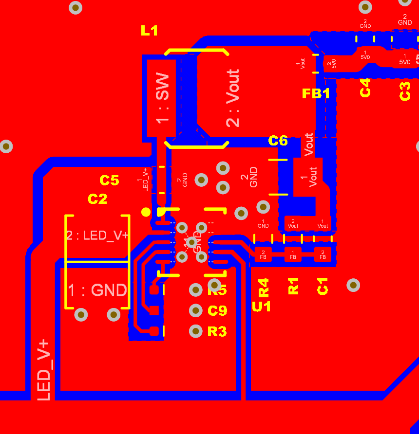
I've got a situation where my input parameters are fighting the design criteria. I know from reading that I actually need to use the LMR16006X part to have the lower 700kHz switching frequency. But with my high input voltage and low output current I keep coming up with very high and large inductors. I read in 1 post that I could "ignore" the web bench calculations and use a smaller inductor and compensate for the increase output ripple with more capacitance.

My mechanical area is restricted so I'm trying to minimize the area as much as possible. I looked at a lot of different switchers and the LMR16006X looks like the best fit but maybe someone knows of another part that might be better (I originally designed in the LM5009MM). The efficiency of the LMR16006X looks much better so hopefully I can just use a smaller inductor?

  • Hello George,

    please can share what values of Lbuck and Cout you intend to use?  Assuming your Vin is 45 to 60V and Iout max is 250mA?

    Thanks.

  • Hi David,

    I am hoping that I can use the Murata 1264EY-101M=P3  which is a shielded 100uH, 460mΩ, 1.2A inductor in a 6.3 x 6.3mm package. 

    The concern I have is that most of the power if from the LCD which will be off most of the time and the load drops significantly when that happens. This is going to be powered by mains so power consumption isn't the highest concern. If the light load is an issue I was thinking I could add a couple of LEDs or a bleed resistor to increase the current draw.

    Best Regards,

    George

  • Hello George,

    Sorry I forgot to ask what your output voltage is?  

    If stability is a concern while having a need for high efficiency at light load, perhaps you should consider the LM5166?  This can be configured as a COT/PFM converter where stability will be less of an issue.  The Light load efficiency and no load IQ is very high/Low respectively.  Also there is a quick start calculator tool you can use for your design approach.

    I will close out the thread assuming you will consider the LM5166?  If you wish to pursue the design with the LMR16006 please reopen this thread and state what the output voltage is?  Thanks.

    Hope this helps?

  • My output voltage is 5V. I did look at the LM51660RC but it had a minimum current of 100mA.

    I just used Webbench for the LM5166 and it shows that I need a 470uH inductor which was my initial problem, 

  • Hello George,

    It appears your max output current requirement is 250mA, and you should be selecting an inductance based on this current, not Iout<100mA?  If you want to use 100mA as your selection you may, even though the cell will go red, indicating that you are using a 500mA device for a requirement that is much lower.

    Please use the Quick start calculator shown here to complete your design using your max output current requirement of 250mA, if that's the case?

    Hope this helps?

  • But with the LM5166 calculator (which is very nice BTW)  it says that I cannot go under 100ma? I am concerned with light loads when the LCD is off. For PFM mode and 100mA current draw it says that I can use as low as 7uH which is great for what I am trying to achieve but I'm concerned about what happens at the 2 extremes of my application, maybe ~30-50mA and then ~15-250mA (different backlight brightness).

    Is the LM5166 definitely a better choice than the LMR16006X? I need to try and finish board layout this weekend.

    Best Regards,

    George

  • Hello George,

    I am not sure where it says you "cant use" the LM5166 below 100mA.   The only thing I can see is that the cell goes red if <100mA is used, probably because this Ipeak min for this device is set to 500mA, suggesting an Iout of 250mA max.  suggest the following to keep the cell from going red.  Select 100mA and select the following.

    1. PFM mode

    2. Fsw = 600kHz

    3. Ilim =  0.5A

    selects Lbuck = 10uH.

    Follow the suggestions in the calculator thereof.

    Hope this helps?

  • Yes, I was using the spreadsheet (which is very nice and if you did not point it out to me I would not have found it). I believe Webbench won't let you create a design with a load of less than 100mA also.

    Availability and size is pretty good for a 22uH and that helps improve efficiency too. Running through the numbers it looks like I need to fix the mode to PFM and I can run at 600kHz to help keep things small.

    Here's the schematic that I worked up last night. I used the adjustable version since it had a little better availability and give me the option to change the output if needed. This doesn't show it but I've got a ferrite bead between the power source (LED constant current driver) and LED_V+. With this switcher would it be wise to add any additional input filtering or do you think it's not needed?

    I followed the layout recommended in the datasheet but the placement of the inductor seemed a little odd to me. Usually I place the inductor close to the switching pin but the datasheet seemed to favor making the ground paths shorter over putting the inductor close. Maybe that's because the currents are relatively low with this part?

    Do you see anything obviously "bad" with this arrangement?

    Thanks again for all your help and especially over the weekend. I did most of the layout last night so all I really need to do is layout this and I should be able to meet my target of finishing the layout this weekend.

  • Hello George,

    The layout looks OK to me.  I would just move the CIN caps down a little, making the Cin+ pin closer to Vin pin.  I would do this for the 100nF cap, I would orientate the 4.7uF such that it moves out of the way allowing you to place the inductor closer to the device and shortening the Switch node pour from Vsw pin to the switch node of the inductor pad.

    Hope this makes sense?

  • OK, thanks for the feedback. This just is different than any other switcher designs I've done. I usually place the parts so the ground pads are on the outside and then place vias right next to the pad so it drops right down to the ground plane.

    I'll be placing copper regions later but what I don't like about this layout is that the input and output caps are right next to the inductor and I'm thinking they're going to pick up the switching noise?

    P.S. I had to edit this post because I can paste a picture and it shows but then when I submit the post the picture goes away so I have to come back and insert a file.

  • Hello George,

    the previous layout was more representative of the layout example in the datatsheet and was better.  I was giving the feedback to jut move the 4.7uF, I would jeep everything else the same.  By moving the 4.7uF out of the way you give more room to bring in the inductor closer.

    Sorry for the misunderstanding.

  • Well I'm probably tired and definitely rushed but this is my latest attempt at trying to make that switching loop nice and compact. It still needs some clean up but from where I'm sitting I think it's "OK".

    Looking at some other layouts for this part I'm not convinced I agree with how the parts are placed. In this layout the switching node goes right through Cin.

    Here's my latest attempt:

    Looking at this I probably could rearrange the FB area and drop it lower so the output caps can be lower to the part reducing that ground loop area

  • Hello George,

    This is what I was trying to describe above.  

  • I see the "paste bug" got you too?! Why can't we just pastes inside the message??

  • Hello George,

    Yes it did :), I resorted to insert.

    Hope this helps?

  • I guess if I switched the 100nF bypass cap to an 0805 package I could do that. I guess I'm wrong to worry about the switching node travelling right through the Vin bypass cap?

  • Hello George,

    Correct, the Vswitch node going between the pads of Cin is not an issue.

    Thanks.

  • Well it's too late to bother to submit these tonight but at least I think it looks OK. It's always best to have a fresh set of eyes on it after a break so we'll see how it looks in the morning.

    I went ahead and changed the output caps from 2 22uF to just 1 1206 47uF. Not the best flexibility but that helped the layout so I guess we'll see.

    Let me know if you see anything bad or wrong!

    Thanks,

    George

  • You do a good job of mimicing suggested layout outlined in LM5166 datasheet.

    Ensure ferrite bead in series with the output is properly rated for peak current limit.

    Schematic didn't show second stage filter, though ensure appropriate damping is performed in accordance to blog:https://e2e.ti.com/blogs_/b/powerhouse/archive/2018/01/18/design-a-second-stage-filter-for-sensitive-applications

    I suggest you proceed in board build after considering above items.

  • Hi Marshall,

    TBH I really don't like that layout. I don't agree that passing the switching node through the input capacitor will not induce noise. But I'm following TI's advice and building the boards like this. I'm not overly concerned because I decided to follow the output of the LM5166 with an LDO that should give me a nice clean stable output.

    I don't foresee my load being any more than 250mA so I've chosen a ferrite bead rated at 1A. I'm using an LC filter so I think that's good although a pi filter would have been better.

    Thanks for the link to the blog post. I have not read that one so it's bookmarked to read when I have time. I'm curious enough about the switcher noise that I might even go back and make a version laid out differently and then compare the 2 designs

    Thanks,

    George

  • Hello George.

    We are hear to help if you run any issues along the way, but just speaking from experience.

    I believe you will be happy with the way the design turns out.