This thread has been locked.

If you have a related question, please click the "Ask a related question" button in the top right corner. The newly created question will be automatically linked to this question.

TPS65131: -Unstable output voltages

Part Number: TPS65131

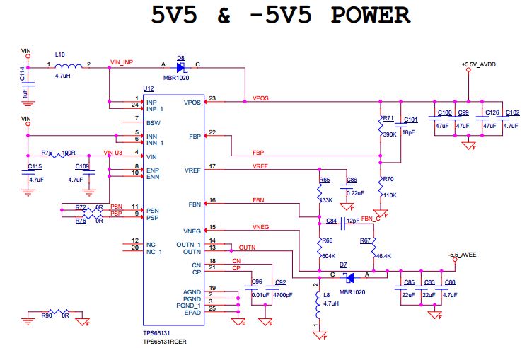
We have a circuit using TPS65131RGER ( buck-boost dual converter) designed to get output voltages of +5.5V and -5.5V. The input voltage (VIN)  to this IC is 5V.

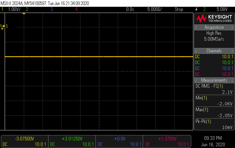
We are getting a DC RMS voltage of 5.43V output at positive output pin(VPOS) and a DC RMS voltage of 2.1V  at negative pin (VNEG). We have attached  the images of the readings along with the schematics image. 

Please let us know the reason and solution for this problem

  • Hi,

    I have notified our expert regarding this topic. Please expect a response by 6/18/20.

    Thanks,

    Aaron

  • Please let me know if you need any further data required and respond us with the solution or method to analyse the issue as soon as possible 

  • Hello Anto,

    I do not see anything major wrong with your schematics but did notice couple of points:

    - The output capactance for both boost and inverting buck-boost converter are much larger in your design than what is recommended in the typical application circuit int he datasheet (22uF). Can you please reduce the output capacitance to 22uF to see if it improves the behavior you are seeing? I am thinking that too much capacitance at the output may impacting the stability pf the converter.

    - Also, recommended value for C109 in the datasheet is 100nF. Can you please change this capacitor to 100nF to see if it impacts the behavior in any way?

    The rest of the schematics looks ok.

    Kind Regards,

    Liaqat

  • Hi Liaqat,

    Thank you for your response.

    The issue is solved. the problem was due to improper soldering of Inductor L8 in OUTN Pin. When we re-soldered it we got the output correctly. 

    We have changed  C109 to 100nF. We have maintained the output capacitors in VNEG pin and replaced the output  capacitors in the VPOS pin with exactly same number and values of capacitors in the VNEG pin. Even with these (two - 22uF and one 4.7uF) we had obtained ripples with in the limit of 5%. If we reduce the capacitor value the ripple increased. So we cant reduce the capacitor values. 

    Anyway we have got the output correctly(with in the limit of 5%).

    With Regards,

    Anto Jacob.