This thread has been locked.

If you have a related question, please click the "Ask a related question" button in the top right corner. The newly created question will be automatically linked to this question.

UC2843: Noise Immunity

Part Number: UC2843
Other Parts Discussed in Thread: UCC2895

Dear Team,

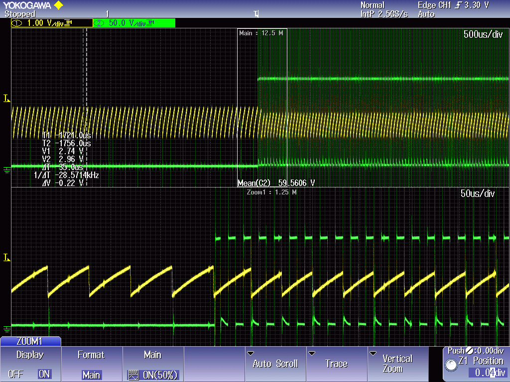
We find the UCC2895 PSFB's Vds(CH2 green) noise will affect UC2843 Buck's Pin4 triangle waveform(CH1 yellow), so the Buck duty will be abnormal

As you can see waveforms, when the Vds is not switching the triangle waveforms don't have noise.

Do you have ideas how to solve the PSFB Vds noise, or how to improve the Buck's noise immunity?

Buck:500~1200Vdc==>225Vdc
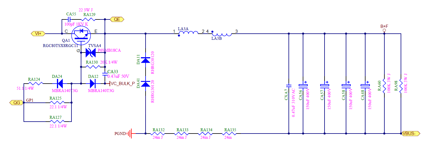
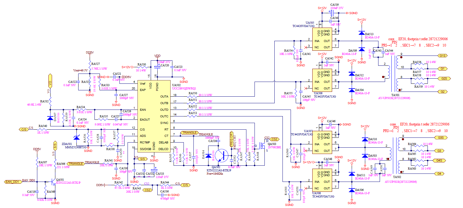
PSFB:225Vdc==>48Vdc

Waveform:

BR

Kevin

  • Hi Kevin

    The PCB layout is the most likely cause of this problem. Track inductances (red) in the source or drain of the MOSFETs in the H bridge will generate large voltage spikes as the devices are turned off. Stray inductance in series with the transformer primary is not a problem because it appears in series with and adds to the transformer leakage inductance (and external shim inductor if you are using one). - see image below.

    Your Vds waveform appears to be really, really noisy so my preferred solution would be to look closely at the layout and see how it can be improved.

    The other factor is if any of the currents in the PSFB ground - between Vin, QB and QD - flow in the ground paths of the Buck controller. The large pulsating currents can cause voltage drops across PCB tracks which can add to the voltages at the pins of the Buck controller. Again the PCB layout is the main factor here.

    If you can't or don't want to change your PCB layout then here are a couple of things you can try:

    Improve the filtering on the current sense signal. Make sure that  CA72, CA37 are located AT the ISENSE pin of the controller with a very short connection to the GND pin. You can try to increase the value of the capacitors and the value of the resistor RA48. You can probably double the value of both without causing too much change to the controller behaviour - check light loads where the duty cycle is smallest.

    Add a small capacitor (100pF to 300pF) between COMP and GND pins of the buck controller - again this should help to reduce the amount of noise at the COMP pin and so reduce the amount of noise at the inputs to the PWM comparator in the controller.

    Add a small capacitor (100pF) from Drain to Source of the FETs in the H bridge. This will slow the dv/dt rate of the spike on the drain and should reduce the amount of noise it injects into the buck controller. The disadvantage of doing this is that the PSFB will lose ZVS at a higher load and the light load efficiency will be reduced.

    Please let us know how you get on.

    Regards

    Colin

  • Dear Colin,

    Thanks for the input, for add a small capacitor (100pF) from Drain to Source of the FETs in the H bridge. 

    Is add cap at each FET at the H bridge(totally 4)?

    BR

    Kevin

  • Hello Kevin

    Yes, 4.

    Alternatively you could add one cap ( 2 x 100pF = 200 pF) across QB and one across QD to get the same effect.

    Regards
    Colin