This thread has been locked.

If you have a related question, please click the "Ask a related question" button in the top right corner. The newly created question will be automatically linked to this question.

TPS63020: Buck Boost Design is powering an MC60 GSM/GPS Module. Has 1.6A burst current and average 1A consumption. The TPS63020 goes into 900mV output after the 1.6A burst transmission

Part Number: TPS63020

Hi, 


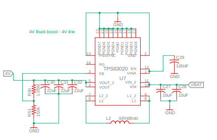
PFA images relating to the schemtic design of the the TPS63020 buck boost IC. 
Buck Boost has been designed with the following specifications - 
Vin (Min) - 3V Vin(Max) - 4.2V 
Iout = 2.1A Vout = 4V 

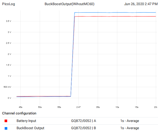
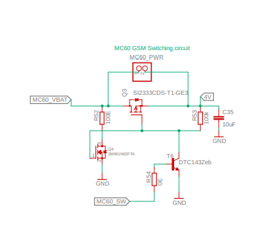
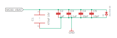
This buck boost powers the MC60 GPS/GSM module which has an average 1A current consumption and a 1.6A bust transmission. 
The buck booster is seen to go into an output state of 900mV after this 1.6A burst transmission. 
We have isolated this problem to the Buck Boost TPS63020 IC output itself. 

Let me know if there is anything I have overlooked. Is there anything that I could modify in this exisiting circuit so as to resolve this problem. 

Looking forward to your reply!
Your support would be appreciated a lot. Thanks. 

  • Hello Milind,

    Please measure the input and output voltage of TPS63020 when the problem occurs with an oscilloscope.

    In your schematic I can find the signals MC60_VBAT and MC60_SW. Please explain to me what these are doing and if possible measure these as well with VIN and VOUT.

    If you can measure the current flowing on the 4V line, this would be interesting as well.

  • Hi Brigitte, 

    Thank you for your reply!
    Shall measure these parameters and provide the same in a while 

  • Hi, 

    MC60_VBAT powers the MC60 module. This line connects directly to the MC60 Module. The MC60 requires 4V.

    MC60_SW is used to programatically switch on and off the MC60. However, for debugging purposes, this circuit is not populated on the board and the MC60_PWR header is shorted with a jumper. 

    PFA oscilloscope readings of Input/Output readings of the Buck Boost IC. 
    I have recorded two scenarios. 

    1. MC60 VBAT line connected to the BuckBoost Output (4V) 


    2. MC60 VBAT line not connected to the BuckBoost Output (4V) 

    We can notice here that the BuckBoost output in scenario 2 drops to around 1V once the MC60 module activates. 
    Kindly provide your insight regarding this. Thanks!

  • Hello Milind,

    Is it possible that MC60 is drawing a lot of current when there are 4V applied to it? Could you measure the current with an oscilloscope going into the MC40, when you supply it directly from a power supply?

  • Hi Briggite, 

    Added two 1000uF caps on the MC60_VBAT line. This resolved the issue. 

    Thank you for the support. 

    Regards, 
    Milind M 

  • Hello Milind,

    Thank you very much for the update.