Other Parts Discussed in Thread: BQ25886
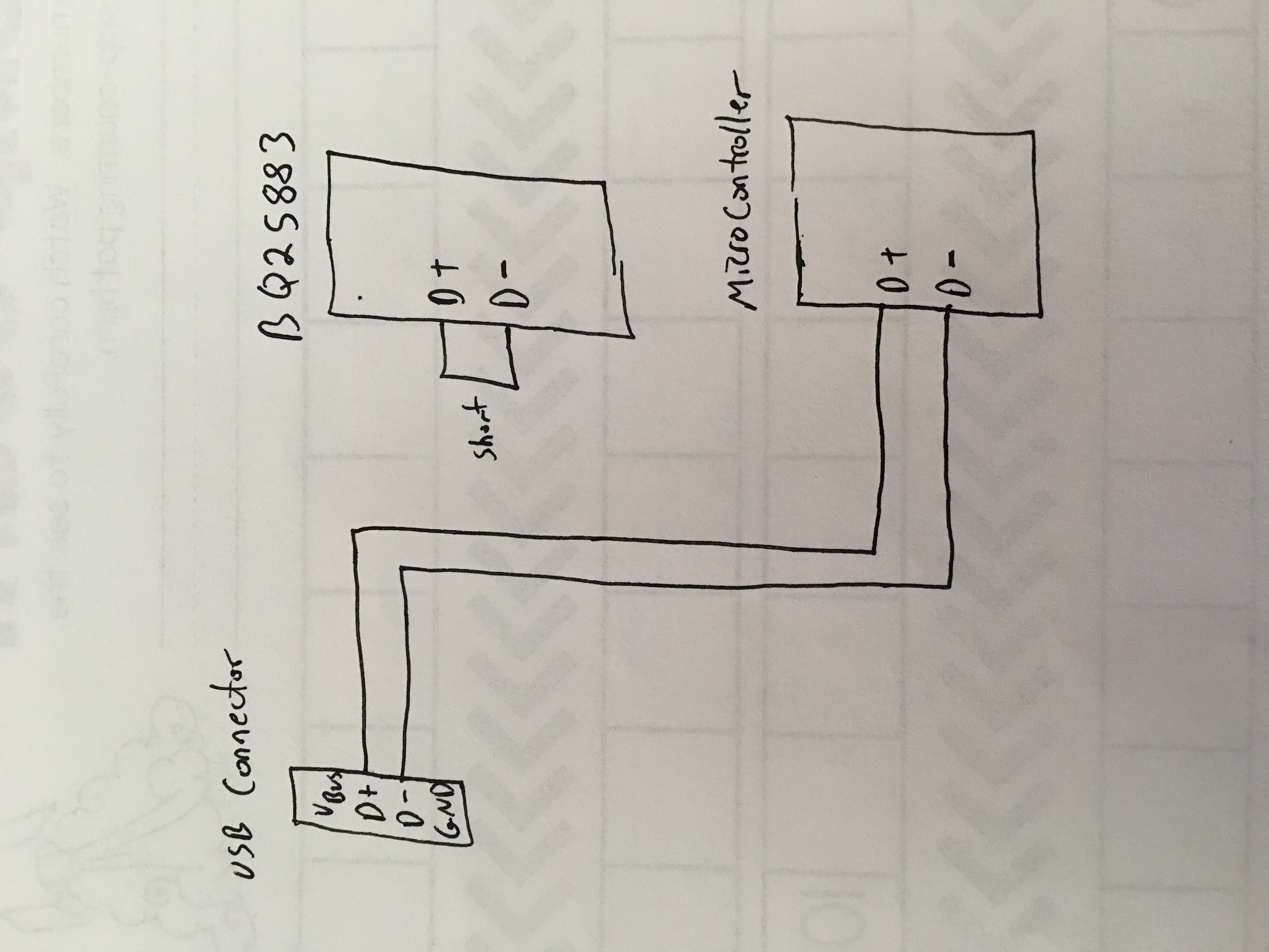
We are looking at using the BQ25883 as the battery charger for our design. We know the chip uses the D+/D- USB lines to perform the input source detection and perform the BC1.2 communications which we need, but we also need to transmit USB data from our onboard microcontroller (our device will be acting as the USB device or slave) to a PC using the same D+/D-. Can the D+/D- lines be shared between the charger and a microcontroller? What is the best way to implement this? Will the computer still allow a device to enumerate and perform data transmission after the BC1.2 communications?
I've seen in the forums this question on a similar device, the BQ25886, where it was stated by a TI Employee the D+/D- lines go in high impedance around 1 second after connection. But this is not documented anywhere in the datasheet that I can find. Does that also happen with this device?
https://e2e.ti.com/support/power-management/f/196/p/862179/3189193
If a MUX is the recommended way to go, how or who do you recommend to perform the MUX switching? How do you know when it's an allowed time to switch?