I am using a TPS7A3301 for a design. It keeps failing and I don't know why. The input voltage is -34VDC. The voltage set resistors are 1.15M and 43.2K to give me -32V out.
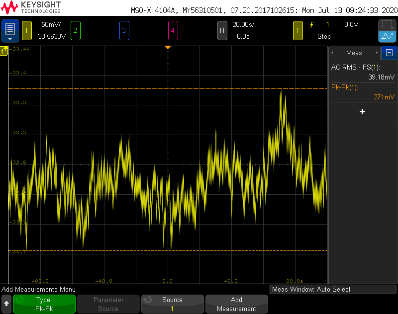
The effect of the failure is a slow drift in the output voltage that gets worse over time. It looks like this (AC coupled) after the regulator has been powered on for a few hours:

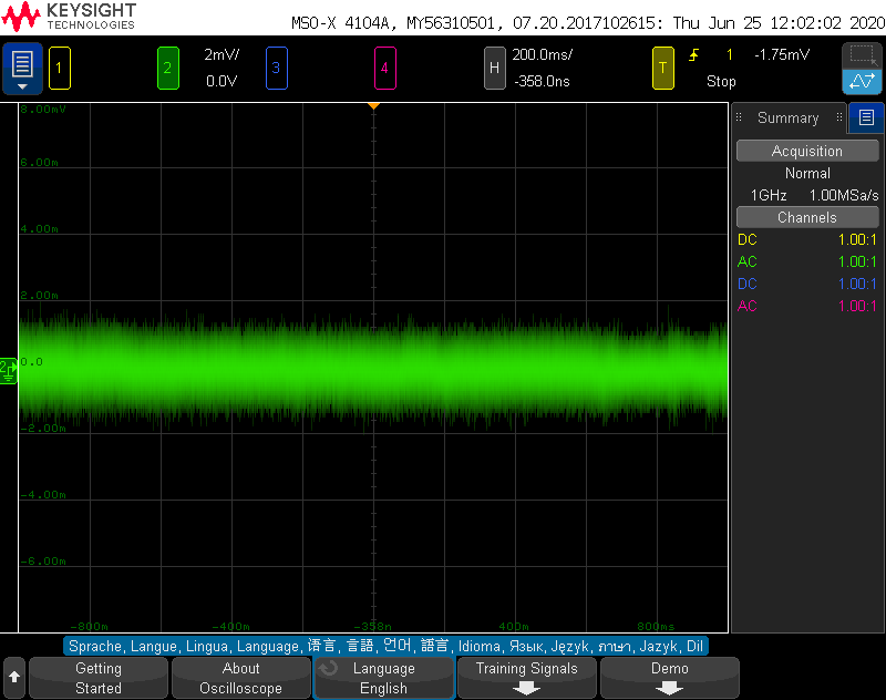
Here is a screenshot from immediately after powering up the regulator for the first time, and you can see the output voltage is very stable:
This regulator is used to power some opamps. The input signal to these opamps is powered by a separate set of supplies than the -34VDC. I discovered that when I powered on this set of supplies before my -34VDC supply, a spike occurred on the regulator output that violated the TPS7A3301 absolute max spec for output to input voltage. I corrected this by ensuring that the -34VDC supply was always powered on first, but this did not fix the problem. I also removed the feed forward capacitor from the regulator circuit, but this also didn't correct it. I did this after reaching out on the TI support forums, which you can read here: https://e2e.ti.com/support/power-management/f/196/p/904311/3342560#3342560
Below is a schematic of the regulator circuit. FWIW, I'm using the same regulator elsewhere in the design, with -20V in and -18V out, and it isn't experiencing this problem.
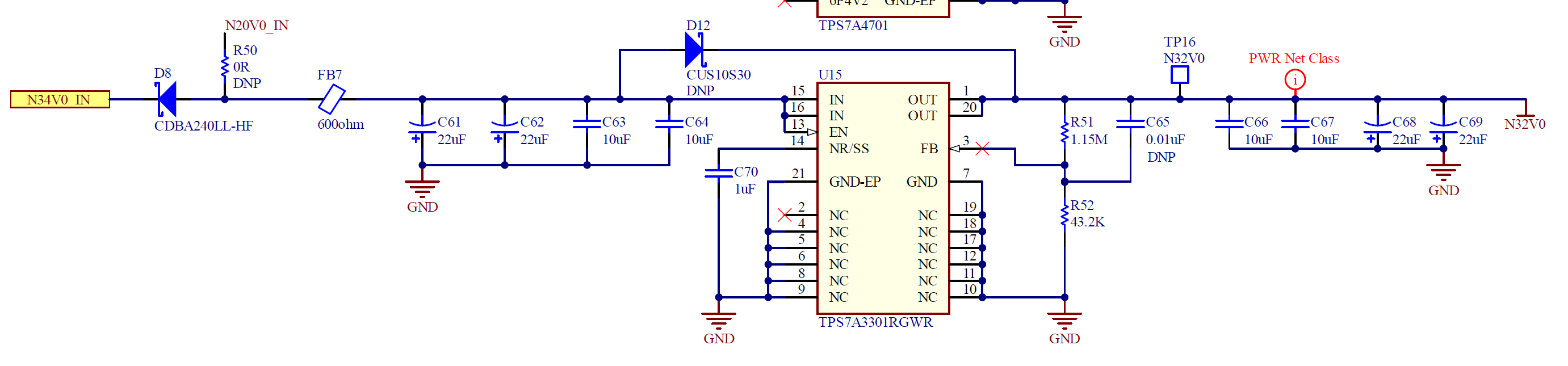
You may note the bypass diode D12. This is not populated, but I did try populating it and it did not prevent the problem.
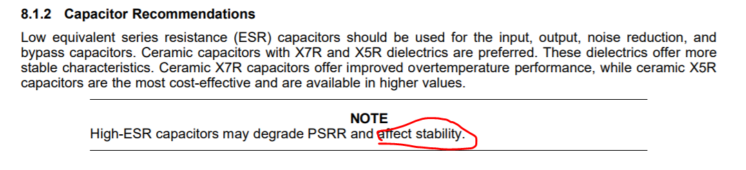
I've measured all the absolute maximum specs and I don't think I'm violating any of them. My only guess at this point is I am using two KEMET T491X226K050AT 22uF tantalum caps on the input and 2 on the output, in addition to two 10 uF ceramic caps on the input and output. These tantalums have an ESR of 0.7 ohm at 100KHz. Maybe this is a problem since the datasheet recommends ceramics.
Appreciate any advice or ideas you can provide. Thanks.