This thread has been locked.

If you have a related question, please click the "Ask a related question" button in the top right corner. The newly created question will be automatically linked to this question.

LM66100: LM66100 Application use as Diode Oring.

Expert 2385 points
Part Number: LM66100

Hi,

Please help to advise on the application LM66100 use as diode oring.
We are wonder that whether it is able to use LM66100 as diode oring for the below scenario:

(1)2 power sources with same voltage level and one sharing load; The load current have to sharing with this 2 power source at the same time (50% 50% or etc) along the period.
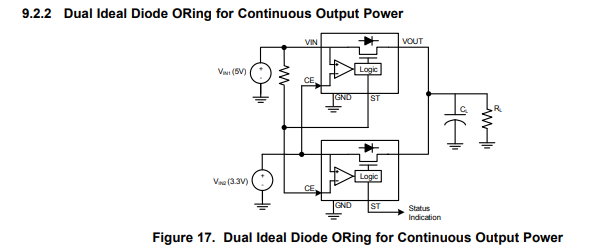
Below the example from datasheet.
If I am understand correctly, the diode oring below application is switching in between 1st and 2nd power sources when the either Vin1 – Vin2 > Vce threshold (80mV) or Vin2 – Vin1 > Vce threshold (80nV) condition are met.

Our question is, If the switching frequency between source 1 and sources 2 is normal and acceptable and what’s the output filter cap value should have for say the load current max 800mA for not being interrupted.
Also is there any better way and idea design application use LM66100 for this scenario (not always switching) due to same voltage level power input sources.


(2)1 power sources with backup supercap and one sharing load; The load current is only sharing with this backup supercap at the event when there is a burst which main power sources not able to sustain for a short duration:
After the short burst duration the supercap will be charge back by main power source with the same voltage level at the end.

The same question also about the how LM66100 diode oring to differentiate when there is the needed and burst require only especially both have the power source and backup supercap have the same voltage level.

  • Hi Electrobud,

    LM66100 cannot perform any load sharing when used in an OR-ing configuration. In fact, LM66100 is not recommended for any load sharing applications.

    This configuration only allows 1 device to be ON at any given time. Both device will not be ON together and allow for "load sharing". I do not think LM66100 will work for these scenarios.

    Please refer to this app note for more information on load sharing: https://www.ti.com/lit/an/slua550/slua550.pdf

  • Hi Shreyas,

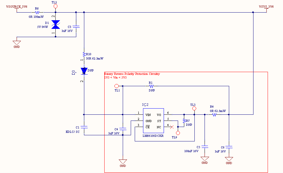
    Thanks for the information. Need your help to comment on the below schematic LM66100 application for the scenario (2) use, will like to know whether is this workable?

  • Hi Electrobud,

    LM66100 is set up for Reverse Current Protection here. Is this your intent?

    You have set the device up similar to Figure 13 on the datasheet. This is Always-ON reverse current blocking. When V0 rises higher than Vin, reverse current will flow. For LM66100, 0.5A of reverse current can flow from VSYS_3V6 to TL1 before the device will turn off. Is this acceptable for your system?

    If so, then LM66100 is set up correctly for RCP.

  • Hi Shreyas,

    Do you mean the reverse current flow will conduct from VSYS_3V6 to TL1 before the device will turn off when the R1 DNP?

    My intention and application is to have use LM66100 for the purposed of 1 power sources with backup supercap and one sharing load.
    The load current is sharing with this backup supercap at the event when there is a burst which main power sources not able to sustain for a short duration. In this case the LM66100 should turn ON during Vce<Vin -250mV (during burst)

    While in normal circumstance and Vsource3V6 dominant, the LM66100 Vce>Vin+80mV in turn off mode (no reverse current flow backward through LM66100) and there will be some minor current flow through via LM66100 forward body diode.


    Please let me know is this the correct and proper way can the LM66100 application use for?

  • Hi Electrobus,

    I am assuming that R1 and D3 are DNP. I am also assuming that VSOURCE_3V6 > TL1.

    Let us consider the case where VSOURCE_3V6 is disconnected and where the supercap at TL1 is supplying current to VSYS_3V6.

    Now when VSOURCE_3V6 is connected and becomes "dominant", VSYS_3V6 > TL1. 

    In this situation reverse current will flow from VSYS_3V6 to TL1 until Vce>Vin+80mV. Due to the low R_on of LM66100, this reverse current can be 0.5A.

    After LM66100 turns off, no reverse current will flow through the device. The body diode is also positioned in a way that blocks reverse current in this device.

    Right now the device is configured for the above .

    You said "The load current is sharing with this backup supercap at the event when there is a burst which main power sources not able to sustain for a short duration. In this case the LM66100 should turn ON during Vce<Vin -250mV (during burst)". I want to point out that the only time when LM66100 will turn on is if the output voltage drops below the 250mV threshold. If the output voltage does not fall during these "burst" events then LM66100 will not turn on.

  • Hi Shreyas,

    Thanks for the detailed information. Please find my below reply in blue.

    Yes, and agree to you.

    Let’s now consider the diode D3 populate and R1 remain DNP. The diode serve as forward charge to the supercap from the Vsource_3V6.

    Due to the natural properties of D3 diode forward voltage drop >=0.15V and the supercap will never get full charges same voltage level as Vsource_3V6.

    This imply and mean that the supercap will have Vsupercap < Vsources_3V6 – 0.15V and the LM66100 will have never get into the reverse current condition.

    You said "The load current is sharing with this backup supercap at the event when there is a burst which main power sources not able to sustain for a short duration. In this case the LM6610 should turn ON during Vce<Vin -250mV (during burst)". I want to point out that the only time when LM66100 will turn on is if the output voltage drops below the 250mV threshold. If the output voltage does not fall during these "burst" events then LM66100 will not turn on.

    Noted and agree to your point.

    How’s about consideration including the internal body diode of LM66100.

    Will this body diode will conduct and sharing portion of the current to the load even during LM66100 in turn off mode (Vsys_3V6 > Vsupercap) through forward bias internal body diode of LM66100?

  • Hi Electrobus,

    The body diode for LM66100 is place from input to output. This means that when VSYS_3V6>V_supercap, this body diode is reverse biased. 

    In the turn off mode, there should only be small reverse diode leakage which is spec'd in the datasheet as Out to In leakage current.

    Let me know if you have further questions.