This thread has been locked.

If you have a related question, please click the "Ask a related question" button in the top right corner. The newly created question will be automatically linked to this question.

UCC28251: RT function discussion

Part Number: UCC28251
Other Parts Discussed in Thread: UCC28951

Hi team,

It is nice to know you here. My customer has two questions about the UCC28251 RT function.

1. Is RT pin internal circuit a current source or voltage source? What is the voltage/current source? 

2. What is the trigger principle to let this IC enter synchronization mode?

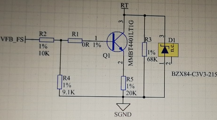
My customer does not apply an external clock to RT pin, they want to realize shift frequency, so they use Triode on/off to get different RT resistors and get the different frequencies. Sometimes they find that this IC will enter 42kHz during start-up (target frequency is 100kHz), RT voltage is 0.5V(normal voltage is 1V), this is the clamping frequency claimed in our datasheet. Do you have some ideas about how ICwenter this mode? Thanks.

BR,

Charles Lin

  • Hello Charles,

    The RT pin of the UCC28251 has current source output which is powered by the 3.3V internal voltage reference.

    For external synchronisation you will allow the UCC28251 to operate with a free running frequency about 10% less than the synchronisation frequency
    This allows you to select the RT resistor value.
    The synchronisation pulse need to be at least 1V high for to set the oscillator
    And it needs to be at most 0.2V high the remaining time

    It seems like your application is running at the minimum oscillator frequency at startup.
    I recommend that you set RT for 100kHz free running frequency and then synchronise with a 110kHz external frequency.

    Regards

    John

  • Hi John,

    Maybe I didn't explain the customer's question clearly. They do not have a synchronous clock input here, they use below circuit to do frequency shift function.

    1. The VFB_FS is related to COMP, the higher the COMP voltage, the lower the VFB_FS voltage, the lower the frequency will be;

    2. The max frequency is R3//R5, 377kHz, the min frequency is R3, 103kHz;

    3. Deadtime is 300ns;

    When my customer uses the below circuit, the frequency will be 42kHz  when star-up. We want to understand why this circuit will let IC enter the synchronisation mode, so we have two questions here,

    1. How to let this IC enter the synchronization mode? Just one falling edge of 1V to 0V is ok?

    2. How to let the IC do not enter the synchronization mode?

    Thanks.

    BR,

    CL

  • Hi John,

    Do you have some updates about the issue customer met here? The customer is waiting for our response. Thanks.


    BR,

    CL

  • Hello CL,

    You have not provided details of the VFB_FS signal but most likely
    you are not going to be able to synchronise with an NPN  emitter follower circuit on the RT input pin.
    The base drive current on Q1 is going to super impose a voltage on R5 and prevent Q1 from saturating.
    Since the reference voltage in the UCC28951 is only 3.25V it is unlikely that the signal on R5 is a recognisable sync signal 

    Have you tested the free running frequency with Q1 removed ?
    It looks like this should be about 100kHz.

    Regards

    John

  • Hi John,

    Yes. When we remove the Q1, the frequency is 100kHz. The issue happened by chance, we are also curious about what may cause IC to enter sync mode. What may cause this IC to enter sync mode if no external sync signal applies to RT pin?

    BR,

    Charles 

  • Hi Charles,

    The ic will run at the frequency set by the RT timing resistor if no sync signal is applied.
    This is the free running frequency.

    Regards

    John

  • Hi Charles,

    I am closing this post since we have been corresponding by email.

    Regards

    John