This thread has been locked.

If you have a related question, please click the "Ask a related question" button in the top right corner. The newly created question will be automatically linked to this question.

UCC28881: why the current of inductor turn to DCM after 14.4ms?

Part Number: UCC28881
Other Parts Discussed in Thread: UCC28880

Dear Team,

Here is the transient simulation.The  Run to time(TSTOP) is 40ms and the PSpice A/D result is :

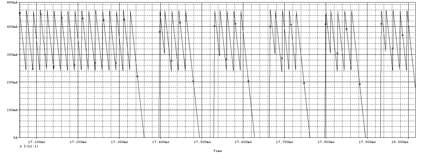
As the plot show,the current of L2 is CCM before 17.3ms,but is DCM after it .Can you tell me why ?Thank you.

Alice

  • Hello,

    The UCC28881 uses an on/off control scheme the inductor current seems to be correct.

    Please refer to figure 13 in the data sheet.  When FB is less than 1V the controller will deliver 62 kHz switching packets.

    https://www.ti.com/lit/ds/symlink/ucc28881.pdf

    There was an application not that was written for the UCC28880/1 to reduce audible noise.  Figure 3 of this application note gives a better representation of how the UCC28881 compared to the data sheet.  Also figure 3 shows output ripple voltage and inductor current.  You will observe that the waveform you are observing in simulation is similar. 

    Regards,

  • Hi,

    Thank you for your answer.It's so cool of the UCC28881 PSPICE MODEL.

    Regards,