This thread has been locked.

If you have a related question, please click the "Ask a related question" button in the top right corner. The newly created question will be automatically linked to this question.

UCC25600: UCC25600 feeback loop design

Part Number: UCC25600
Other Parts Discussed in Thread: TL431

Hello, 

I am trying to design a feedback loop for UCC25600 for a Full bridge LLC Converter for a big automotive customer. My Converter output is 28V, 110A. . My feedback loop looks like this: 

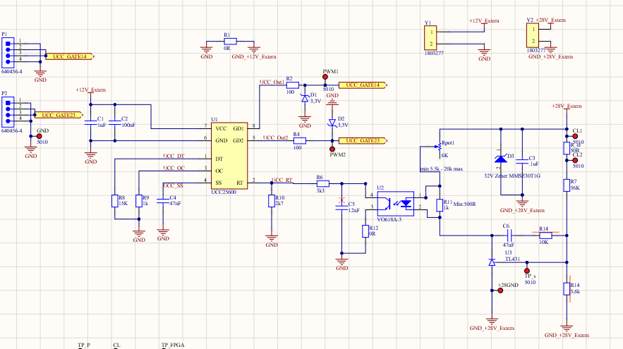
Problem is the controller regulates the output voltage to 28V till 20% of full load afterward it try to sets voltage below 28V. How can I fix this issue? 

I am not an expert of control loop design and would need help your feedback to tune my circuit. Is it possible to tune the circuit using simulations? 

I have seen in the EVAL board you achieved the tuning using NETWORK Analyzer. Can you please let me know exactly what set of equipment you used to achieve the tuning? In that case It would be awesome to know what we would need to buy.  

 Regards, 

  • Hello Sidd,

    Thank you for your interest in the UCC25600 LLC controller.

    With the 2.5V reference of the TL431 shunt regulator, the feedback divider resistors of 56K and 5.6K (R7 and R14) result in a 27.5V setpoint for Vout.
    The regulator will attempt to control the voltage at the point of sensing.

    You did not say how low Vout falls when load is above 20%.  If only to 27.5V, then the regulator is working correctly and loads < 20% have a little positive drift.
    If a volt or two lower, then most likely you are measuring Vout after some significant output resistance which is dropping volts as the load increases.  

    If Vout drops many volts very rapidly when the load increases above 20%, then most likely you are triggering an over-current protection (OCP).
    Either the OCP threshold set-point is too low, or significant noise is getting into your current sense and triggering the OCP.  
    Check the datasheet for information on overcurrent protection.

    Regards,

    Ulrich

  • Hello Ulrich,

    Thank you for your reply. I just checked the schematics and I have a 1.2K resistance instead of 50ohm resistance at R_CL ( above R7). Hence, the TL431 is receiving 2,495V reference and hence I recon output should be 28V.  I am not using the OC pin hence I don't think thats causing the problem. 

    ''You did not say how low Vout falls when load is above 20%.  If only to 27.5V, then the regulator is working correctly and loads < 20% have a little positive drift.
    If a volt or two lower, then most likely you are measuring Vout after some significant output resistance which is dropping volts as the load increases.  '' 

    - Actually the voltage drops 0.1 V for every 5 A current drawn after 20% load mark. I am using a electronic load ( in constant current- resistance mode) and its connected my 0.5m cable. The output voltage is stable but with an increasing error from the required 28V.

    I checked the theory with distance and there is not much voltage drop between load and the rectification stage. I checked with oscilloscopes and accurate meters to confirm that this is in facnt the converter output.  Below are some pictures

    Looking forward to your support. 

    Best Regards,

    Sidd 

  • Hello Sidd,

    The issue is not specifically the distance between the load and the power stage, but the resistance between the TL431 anode point and the R14 GND sense point.

    This minor Vout drop with increasing load is indicative of a voltage drop in the GND path from the TL431 to R14.  As load current goes up through the resistance between TL431 GND and R14 GND, the R14 GND becomes more positive, which would tend to lift the REF side of R14, so the TL431 adjusts the error to reduce Vout to compensate. The GND path difference is gained-up by the voltage-sense resistor ratio R7/R14.

    I recommend to move the R14 GND point back to the TL431 GND, or move the TL431 GND point over to the R14 GND, to eliminate the voltage difference.

    Regards,
    Ulrich

  • Hello Ulrich, 

    Thanks for your insight. I think I found the problem. The problem was my capacitor bank was under-designed and it caused to Vout have a lot of ripple in it causing the the controller to malfunction. I will test some more with bigger capacitors and let you know if the problem persists. 

    Viele Grüße,

    Sidd

  • Thank you, Sidd.

    With that, I will close this thread. 

    Regards,
    Ulrich