Schematic Link: https://a360.co/2XsIdVQ
We are a small automotive electronics company trying to take advantage of the TPS92830-Q1 3-Channel High-Current Linear LED Controller. Our design drives these LED drivers via an Expressif ESP32 microcontroller. Using the microcontroller, we have elected to use a PWM output via the microcontroller pin rather than the built-in PWM feature of the chip since this design is intended to be used in a number of different applications and must be dynamic. I have provided the schematic of the design below which includes our design layout and connections.
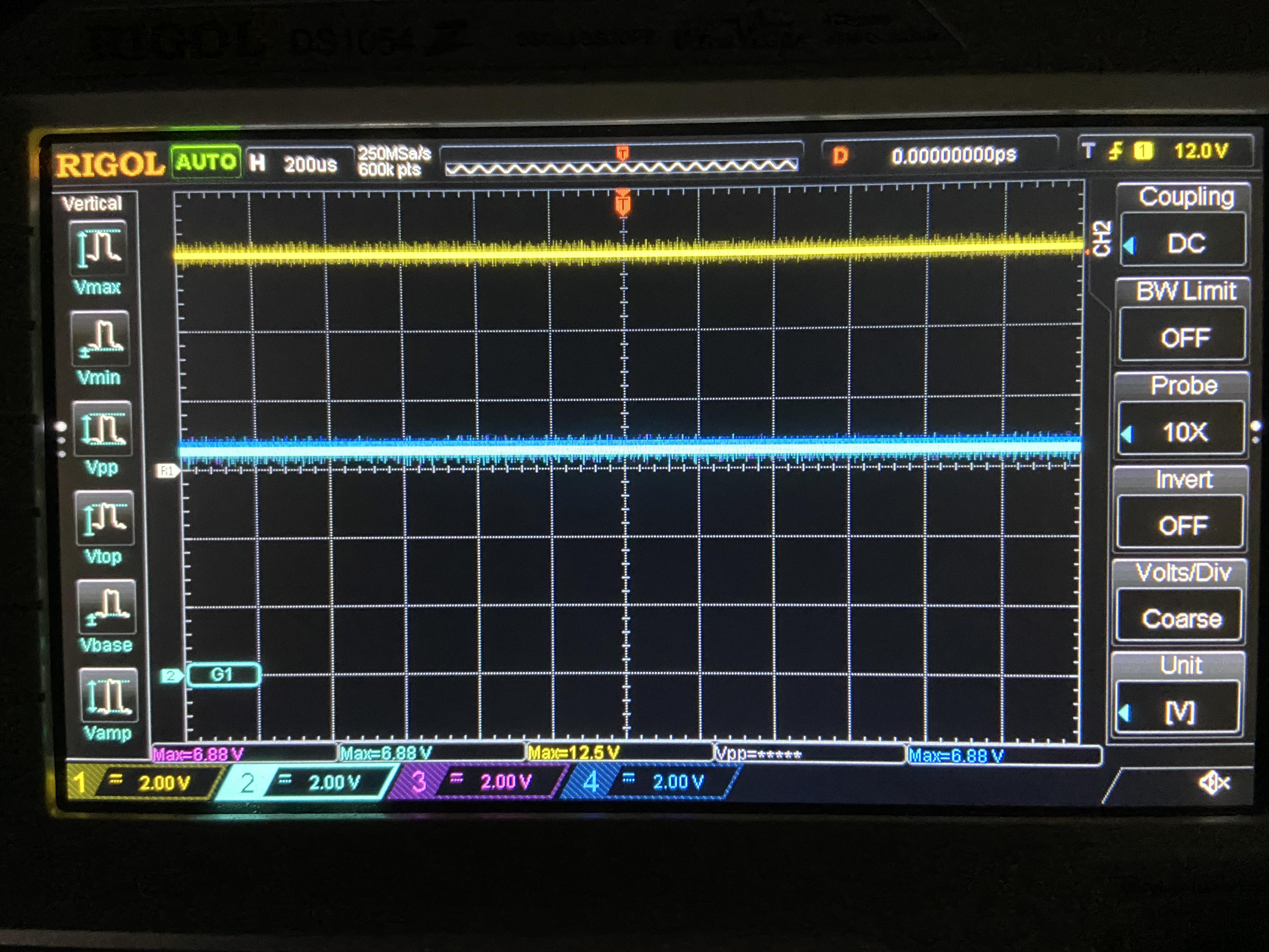
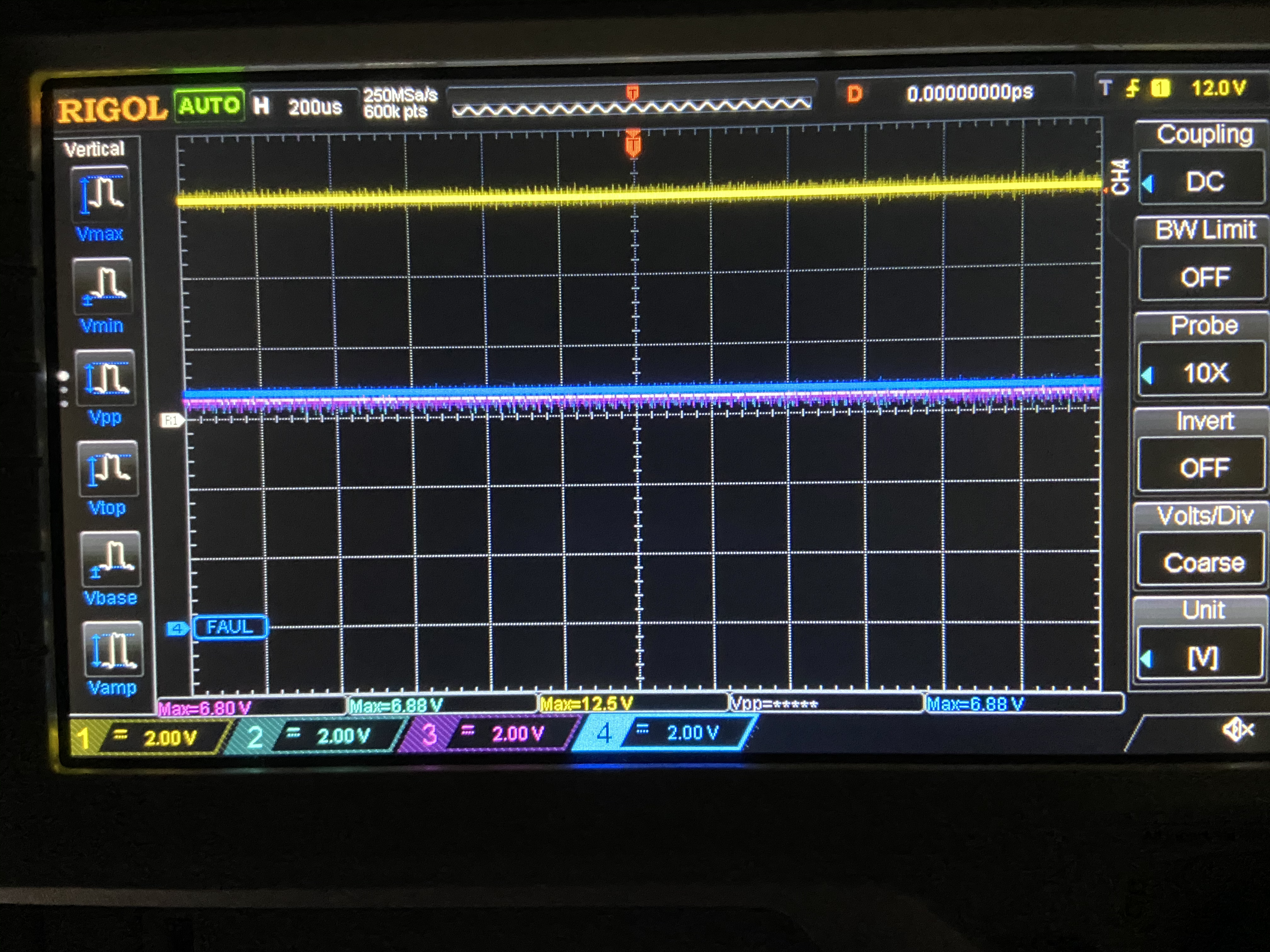
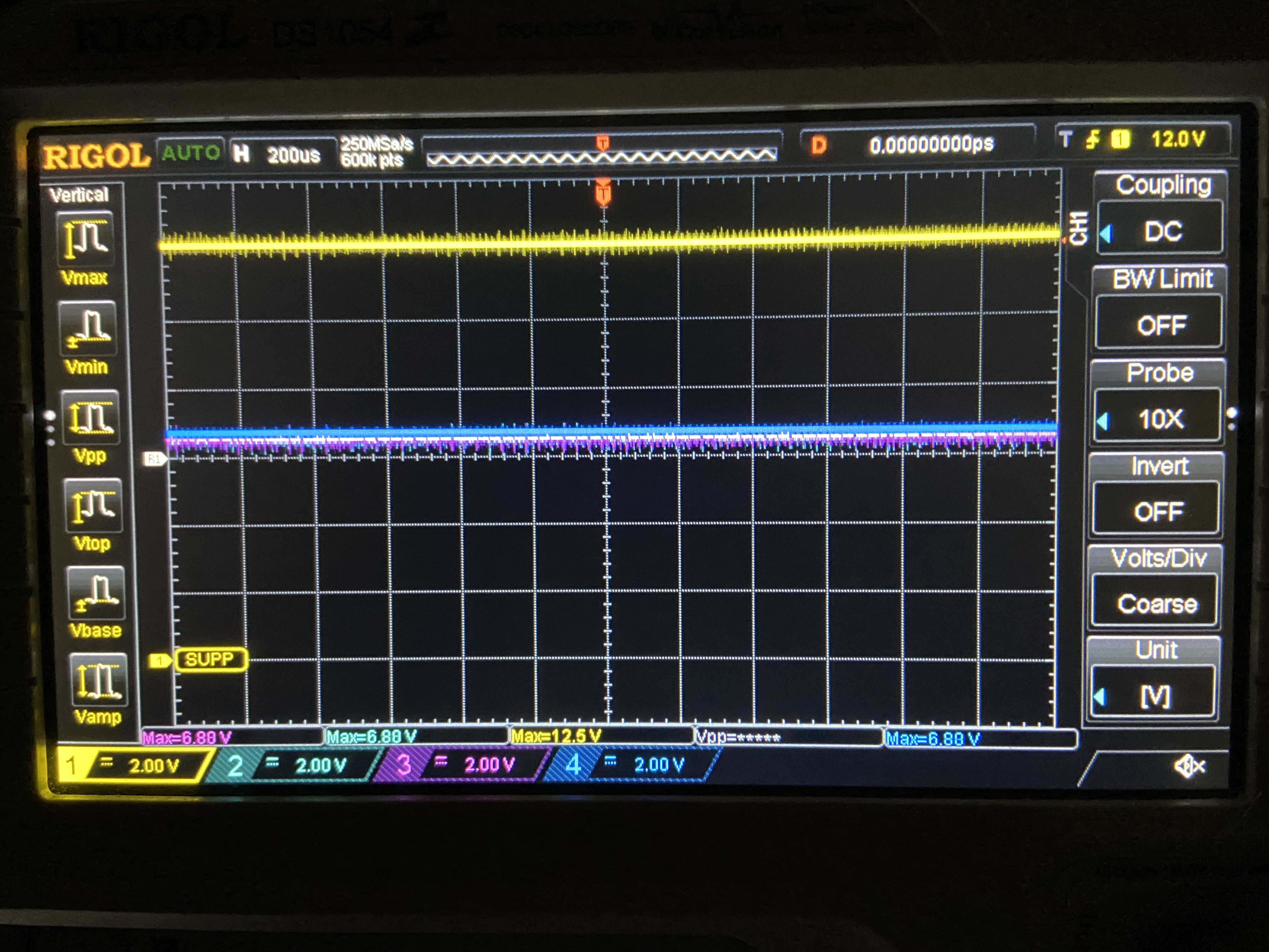
The issues we are experiencing are largely centered around unexpected MOSFET gate voltages (LED driver G1, G2 and G3 pins) which are dependent on a number of factors including the input voltage provided by the vehicle (typically ~12-14 V), the DIAGEN “lower limit” and the DERATE “upper limit.” After verifying the voltage divider on DIAGEN and the DERATE pins, we do not see the MOSFET transistor gate voltage we expect inside the valid voltage operating range.
Here are the requirements our design must conform to that are relevant to our LED drivers:
- The valid operating voltage range is +9 VDC to +16 VDC. Any voltage level below +9 VDC and above 0 VDC will be in a low dropout state. Any voltage above +16 VDC will be derated based on the voltage.
- The LED driver output channels will be matched to different applications based on the vehicle’s lighting requirements. The corresponding sense resistor value will be matched to the current output on the aforementioned channel. For example: A channel that requires 300mA will be paired with a 1 ohm resistor. A channel requiring 500 mA will be paired with a 590 mOhm resistor.
After much trial and error, we cannot seem to render the output voltage from the LED driver that we expect. We have swapped components in fear of DOA devices, confirmed the component values placed match the values on the schematic and various other easy checks and “gotchas” that we may have missed. Our goal with this LED driver is to provide a robust and safe design for customers to use in an automotive lighting solution, but this LED driver has been fighting us every step of the way.
With that being said, I’d like to open up the conversation in this thread by providing our schematic to allow some of you to validate possible errors with the hookup of our device or any other issues you may see with the layout of our schematic. We do have access to an oscilloscope and other electronics diagnostics tools, so oscilloscope images will be provided if needed.