This thread has been locked.

If you have a related question, please click the "Ask a related question" button in the top right corner. The newly created question will be automatically linked to this question.

UCC256301: Bring-up Debug Sequence? No FB voltage

Part Number: UCC256301
Other Parts Discussed in Thread: UCC25630-1EVM-291

I am trying to bring up a UCC256301 LLC circuit. I am wanting to do so "softly" so it doesn't explode if something is wrong. But it seems like the AC circuitry needs to be present to get the zero cross waveforms to begin switching correct?

Anyways, I am using AC input through a PFC stage. PFC gives me 390VDC, all that is working. Now I am trying to get something to switch on the LLC. Monitoring the gate drive waveforms, nothing happens. So I assume the part is in shutdown. I am powering the VCC pin with +15v. I have monitored the +12V output from RVCC and it is stable along with the +15V input (derived from AC source as well). VBLK is 3.84V from my HVDC divider.

I have 100pF hanging off of FB but I am getting 0V out. Looking at the block diagram, that sounds like the reason why it is not switching, but I don't get why not. I have also disconnected the optocoupler (physically) to make sure that wasn't the problem. I expect some voltage out, correct?

  • Hello Nick52556,

    Thank you for your interest in the UCC256301 LLC controller.

    You are correct that this controller needs the AC to be present to function once it is running, but to get it running, you also need to raise VCC above 26V first.

    This is normally handled internally by the HV pin (which charges VCC from the AC line) and VCC automatically rises to the ~26V turn-on threshold before dropping back down to the normal running level.

    If you apply an external fixed 15V to VCC, it will not start.  You need to raise VCC above 26V to trigger the start-up, then drop it back down to 15V.

    However, the controller also needs to see the proper switching signals at its inputs, so if high voltage is not present, it will also not function even if VCC > 26V.
    Also, please reconnect the optocoupler to prevent Vout from rising out of control.

    Regards,
    Ulrich

  • Thankyou for the very quick response.

    Ulrich Goerke said:

    Hello Nick52556,

    Thank you for your interest in the UCC256301 LLC controller.

    You are correct that this controller needs the AC to be present to function once it is running, but to get it running, you also need to raise VCC above 26V first.

    This is normally handled internally by the HV pin (which charges VCC from the AC line) and VCC automatically rises to the ~26V turn-on threshold before dropping back down to the normal running level.

    If you apply an external fixed 15V to VCC, it will not start.  You need to raise VCC above 26V to trigger the start-up, then drop it back down to 15V.

    Oh... Wow. I would have never thought that lol. Can I maintain VCC at > 26V indefinitely? I see the abs max is 30V. So could I run an external 28V supply into the VCC pin and have it always start?

    Ulrich Goerke said:

    However, the controller also needs to see the proper switching signals at its inputs, so if high voltage is not present, it will also not function even if VCC > 26V.

    I was running it with an AC input and with the resistor networks for the high voltage DC. But I am guessing by overriding the input to 15v (through a diode) it never had it's little 26v bump.

    Ulrich Goerke said:

    Also, please reconnect the optocoupler to prevent Vout from rising out of control.

    Regards,
    Ulrich

    I had disconnected it because I thought something was dragging down FB and preventing switching because it was in that "shutdown mode" by pulling FB low. Should I expect no FB floating voltage even when the part is in shutdown (without the VCC going past 26v)? Looking at the block diagram the FB pin voltage is determined from a current source coming directly from VCC. So if VCC is at some voltage, even below startup, would it not output something? I am referencing "Functional Block Diagram 7.2" in the datasheet. I'd expect to see a voltage on FB that tracks VCC by some function, probably linear. So when I see 0v steady, no fluctuations, I am thinking something is externally pulling it low. Can you confirm this is expected behaviour for a sleeping part?

    Thankyou

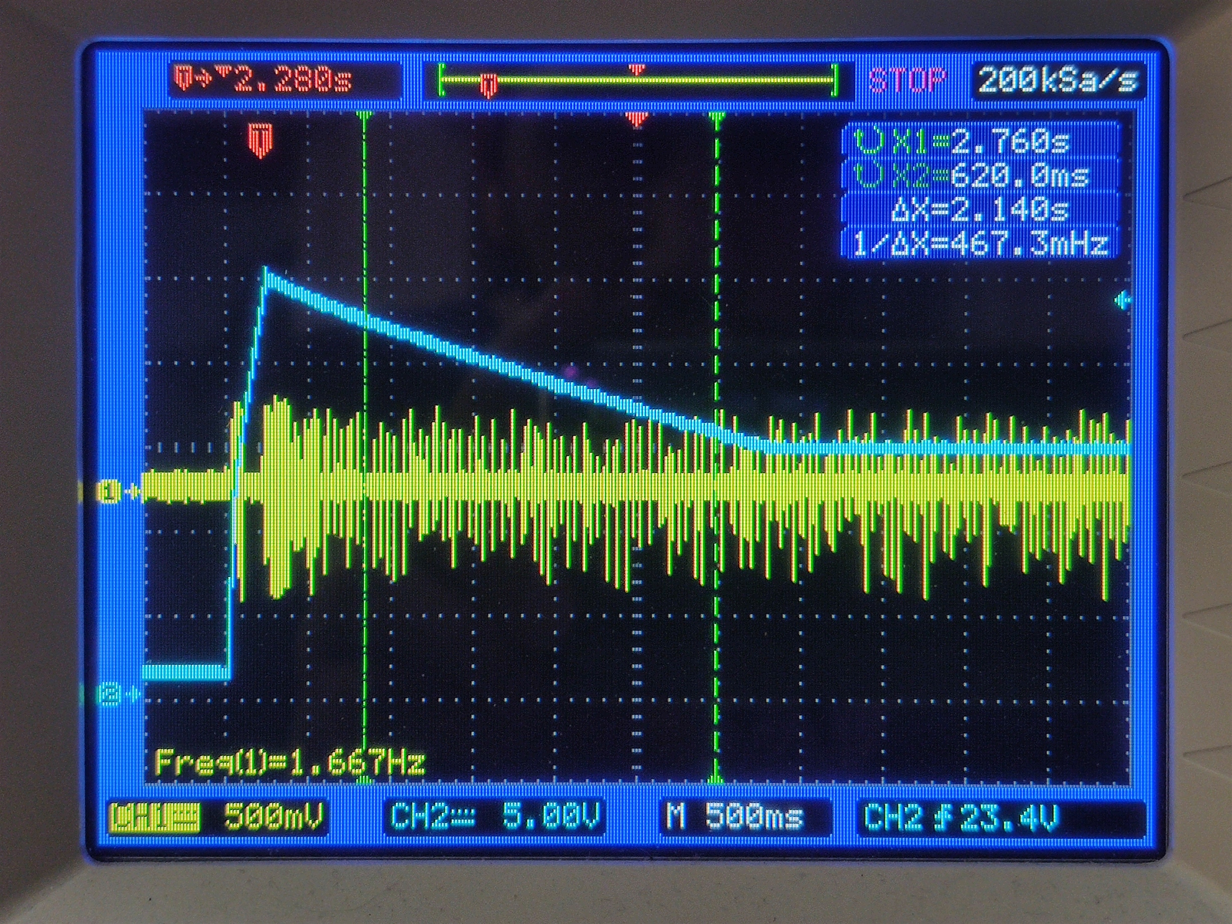
  • I have updated the circuit to allow for the +15V VCC input to go through a diode along with the HV input. It now does startup as you'd say, up to roughly 26V then it decays down to steady 15V which is what I am supplying externally. This is CH2 on the scope. CH1 is the LO gate. It looks like it attempts to switch, or at least there is noise that appears when it should be switching.

    When I trigger on these spikes, it is really just noise. There is no gate drive signals coming out. I have also now looked at the LO signal which stays near ground 100% of the time. Then the HO signal, goes to 10V-ish and stays there 100% of the time. Ideas on what to look at next to see why it is not coming alive? I get no output voltage obviously since there is no switching going on. Input is stable around 380V-390V which is the PFC boost output of a 120VAC input through a AC Lab Power Supply.

  • I am now able to get switching. I had a circuit error that left out 1 of the cascades of resistors to make my VBLK divider so it was over-voltaging and not switching. That has been corrected and now it switches. However it does not regulate or even get close. Wanted output voltage is something is the 200V-300V range (currently set to 230V) and I am getting pulses that bring the average to 9V-20V but the part is obviously faulting and retrying. I can see the gate switches turn off completely for some time, then restart.

    The FB signal looks very DC around 6.2V. Once switching starts it rises up nicely with a minimal C limited ramp and stays steady state until the switching stops and it is pulled low forcibly (not by me).

    Is it safe to assume a fault state is occurring? Are there clues to look for to determine which fault? Are the faults retry-timings slightly different so that I can measure the retry time and figure out where in the state machine it is?

    I looked at ISNS and it looks like garbage, but I don't know what I am looking for. I do see a triangle waveform that rides an unpredictable signal.

  • The OVP fault was tripping using BW input. I don't know why my calculations don't match, but it was getting 4V and shutting down. Since I know I am not experiencing OV on the output, I made the divider a larger multiplier and now it turns on and switches.

    It does not regulate to where I want it to go, but it does appear to be regulating to SOMETHING. I have no idea what though. The troubling thing is that it is sucking a ton of power and the resonant inductance is what is heating up. I mean 90W with zero load. :(

  • Hello Nick52556,

    It is quite evident that something is wrong with the design of the LLC stage. Normal no-load power loss should be measurable in mW, not 90W.

    This problem cannot be debugged from the qualitative descriptions you have provided so far.
    Please compare your LLC design to the UCC25630-1EVM-291 schematic diagram for the basic power-processing and control interconnections.
    https://www.ti.com/lit/ug/sluubq8b/sluubq8b.pdf?ts=1595939327849&ref_url=https%253A%252F%252Fwww.ti.com%252Fproduct%252FUCC256301 

    It is not important that the values and component selections match, but that the interconnections of your design are correct. The actual values for your specific design should be derived from the UCC256301 Excel Calculator tool.

    Use it in conjunction with the datasheet to understand the basic LLC operation, the expected waveforms, and the various specific controller operating modes and functions.  Additional application notes and technical articles are available in the UCC256301 product folder on the TI website: https://www.ti.com/product/UCC256301#tech-docs  

    Also, please check to make sure that the magnetic components (Lr and transformer) are designed to handle the power level and peak currents expected for the maximum output power that your design is required to deliver.

    Regards,

    Ulrich