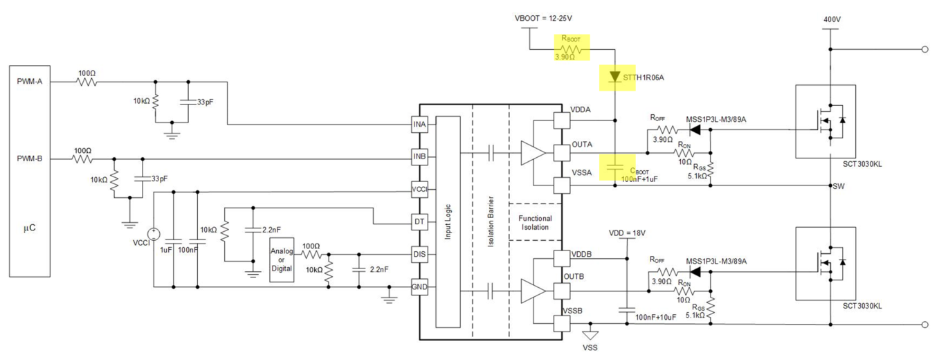
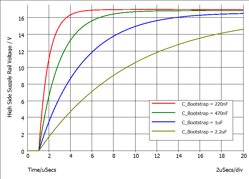
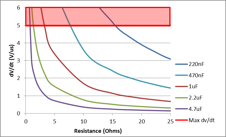
What do I need to know about dV/dt when designing a driver bootstrap supply?

-
Ask a related question
What is a related question?A related question is a question created from another question. When the related question is created, it will be automatically linked to the original question.