This thread has been locked.

If you have a related question, please click the "Ask a related question" button in the top right corner. The newly created question will be automatically linked to this question.

TPS2553: TPS2553 voltage drop after the startup Inrush current limit

Part Number: TPS2553

Hi team,

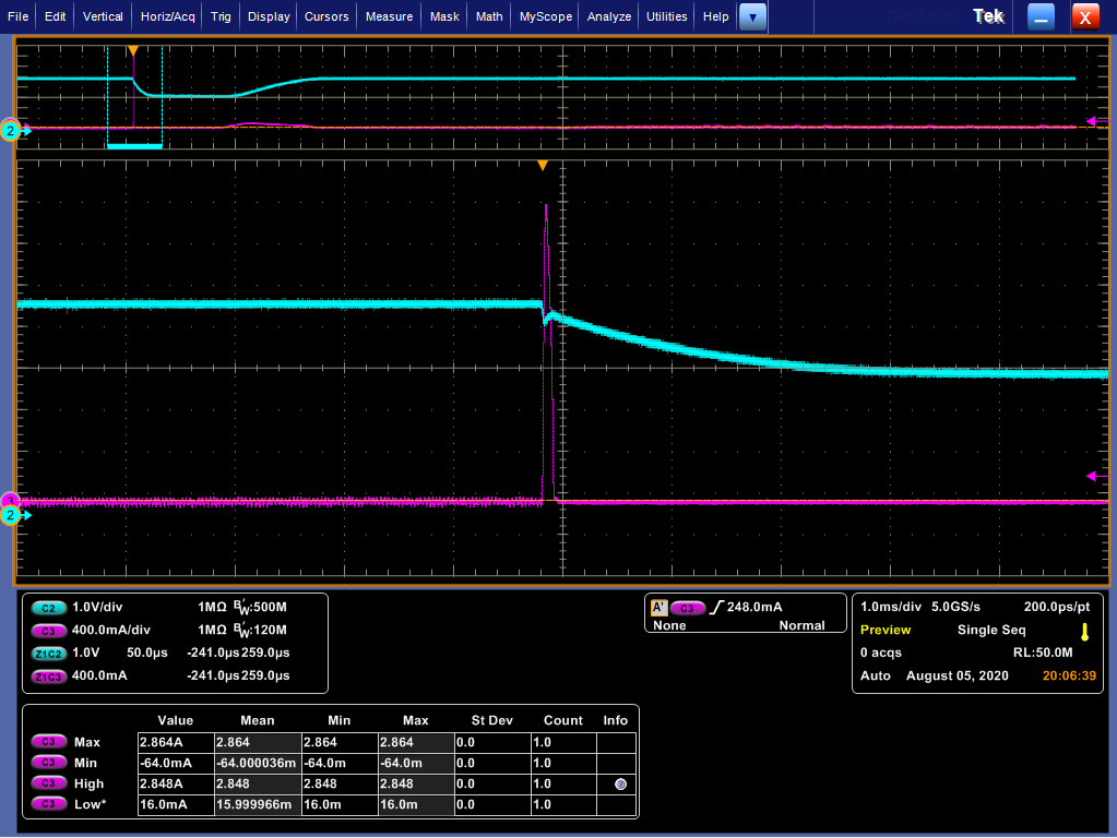
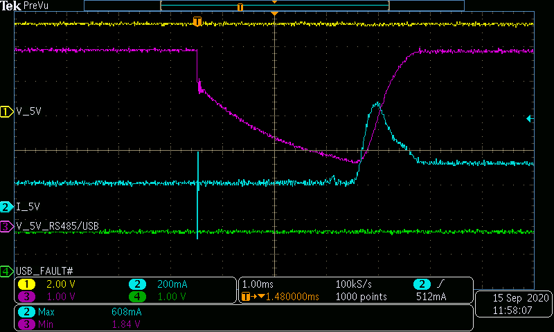
My customer is using the TPS2553 now, the schematic is below, When the load side has a inrush current during startup period. The peak current will be 2.8A  about 150us from the waveform. As you can see the device may trigger OCP, but the Vo start to drop more than 1v when the inrush current disappear. i have let the the customer remove the L53 and use the cable to do the test, the same phenomenon. Do you have some ideas about the weird phenomenon?( in my opinion, the device will not have such large voltage droop with no current limit after the inrush current). Thanks.

(the blue is the output cap voltage, the purple is the inductor current)

  • Hi Frank,

    Try add bigger cap at input terminal side.

    I think it has some loads after the power switch, correct?

    For TI's policy, I will first click resolved button.

    If you have any other concern, contact me any time.

    If you think resolved, please help click 'Issue is solved button'.

    Thanks.

  • Hi Ziv,

    i have let the customer change the input cap to 47uF, still similar phenomenon... i have applied the TPS2553 EVM for them. Could you please also help find more If you can ?Thanks.

  • Hi Frank,

    How do you offer the 5V supply?

    It is suggested to offer single 5V by power supply and have a try.

    If the drop disappear, it means the input cap is too small  and the former DC-DC system triggers protection.

    For TI's policy, I will first click resolved button.

    If you have any other concern, contact me any time.

    If you think resolved, please help click 'Issue is solved button'.

    Thanks.

  • Hi together,

    same problem on our board: Plugging a 44Ohm/10uF-Load into the USB port (as USB2.0 Standard defines for test), the voltage drops down to 1.8V - no voltage drop on the input voltage, to drop on enable, no Fault condition. Only the output voltage seems to have a short cycle:

    Also connected the Enable input to the Inputvoltage (5V instead of 1.8V input) - same behaviour.

    Any explanation or solution found?

  • Hi Raik,

    Try below measures:

    1. Disconnect former DC-DC input and force the VIN by power supply.

    2. Add more cap at VIN and VOUT to have a try.

    I think it's the load transient behavior.

    For TI's policy, I will first click resolved button.

    If you have any other concern, contact me any time.

    If you think resolved, please help click 'Issue is solved button'.

    Thanks.

  • Sorry, but I don't thinks it's the load transient behavior!

    I tried with another board which has the TPS2553DBV as power distribution switch in use. On this board, the input capacitance is 100u+10u+100n and the output capacitance is 100u+2x10u.

    Surprise, surprise - the oscilloscope plots are quiet identical. So the TPS2553 and TPS2553-1 have the same issue.

    I think the chip may have an internal ground bounce issue.

    Proof to the contrary: Using a Micrel MIC2009YM6 instead of the TPS2553-1:

    The current peak is quiet higher (the on resistance is a little bit lower) and there is absolutely no drop to be seen on the output voltage.

  • Hi Raik,

    Our FAE Robert has sent the email to us.

    We will support the case by email.

    Robert will update the status to you later by email.

    I will close the thread first due to the time limitation for E2E cases.

    Thanks.