This thread has been locked.

If you have a related question, please click the "Ask a related question" button in the top right corner. The newly created question will be automatically linked to this question.

LM25088: Voltage drop when load is given at the output

Part Number: LM25088

Hi,

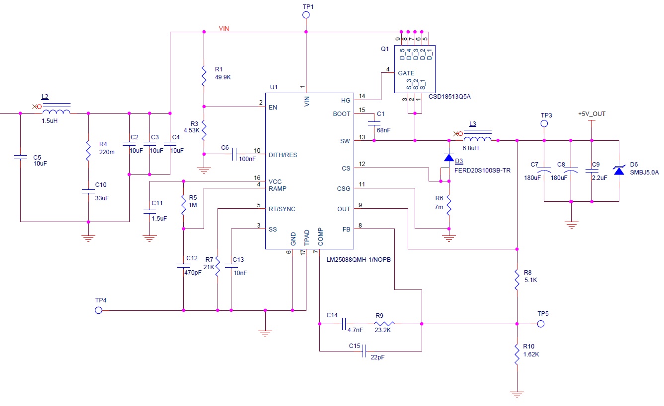
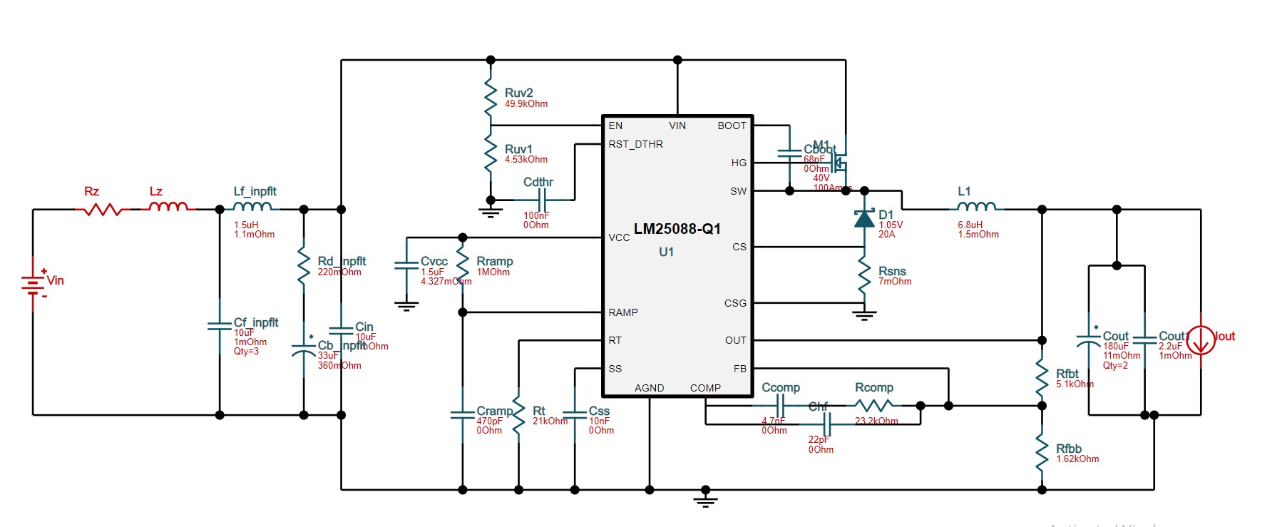
   I used LM25088 converter and designed for 24v input and 5v/10A. The output is at 5V at no load but, when we start to increase the load after 0.7A point the output voltage suddenly drops to 1.2V. I used webbench to design the circuit. Below is the circuit, i also observed the switching frequency dropping from 250khz to 15khz when its going into 1.2V. Kindly help

Thanks and Regards,

Vara

  • Hello

    It sounds like it may be going into current limit.

    First use the component calculator to double check your component values.

    Also, check to make sure that your input voltage is not falling.

    Please send a scope shot of the SW node for both normal and bad conditions.

    The connections to the sense resistor must be "kelvin" to get an accurate measurement.

    Please send a snapshot of your PCB layout.

    Thanks

  • Hi Frank,

        Thanks for the reply.

    It sounds like it may be going into current limit.

    Agreed, but i tried changing the Rsense but did not affect in anyway.

    First use the component calculator to double check your component values.

    Sure will do it.

    Also, check to make sure that your input voltage is not falling.

    Input is stable.

    The connections to the sense resistor must be "kelvin" to get an accurate measurement.

    The connections were not kelvin at first but later changed the connection externally by 2 wires.

    Please send a snapshot of your PCB layout.

    Regards,

    Vara

  • Hello

    Can you send a schematic that corresponds to the layout.

    Did you mean that the output drops with 7A of load or 0.7A ??

    Thanks

  • Hi,

    Output drops after 0.7A.

    Shematics:

  • Hello

    Here are a few more thoughts:

    1. Please double check your design with the calculator tool on the website

    2. I do not see the sense lines to R6.  Both pin 11 and pin 12 must be dedicated traces going to R6.

    3. When the output drops, check if the SW waveform is stable.

    4. Double check the value of C1.

    5. Check the voltage on the VCC pin during normal and bad behavior.

    6. The layout is a little hard to read; can you send a higher res picture.  Or Altium file.

    7. You may want to modify an EVM with your components and check.

    Thanks

  • Hi,

       I have rechecked the design and it seems correct. The kelvin connection is made on the board with 2 wires.

    Hope this resolution is fine.

  • Hello

    1. Check the switching wave-forms during load testing to see if the device is stable.

    2. The input caps are somewhat far from the IC and FETs; and I dont see a high frequency input bypass cap on the IC.

    this may contribute to instability.

    3. You may have to get an EVM as a clean starting point and modify to your application and test.

    Thanks

  • Hi Frank,

       Thanks for the support. The issue turned out to be not having proper kelvin connection for sense resistor and trace width for designed current missed in few places in the PCB layout. We rectified and it works fine now.

    Thanks and regards,

    Vara