This thread has been locked.

If you have a related question, please click the "Ask a related question" button in the top right corner. The newly created question will be automatically linked to this question.

TPS92692-Q1: some issues in electronic test

Part Number: TPS92692-Q1
Other Parts Discussed in Thread: TPS92692

Hi there,

My design with TPS92692-Q1 has 3 questions below. Could you please help to resolve? Thanks.

Parameters:

input: dc12V

function1: day driving light, output 350mA, 12V

function2: position light, PWM dimming, 80% duty cycle

1. Flicking when using 'DC12V, 100Hz, 80%PWM' as input

2. Flicking when adding superimposed alternative voltage with '15Hz-30KHz, Vpp=6V'

3. How to let it works at an input of dc 4.5V ?  

Looking forward to your reply. Thanks.

BR

Han

  • Hi Han,

    Are you using the PWM dimming FET in your circuit?

    In general, the loop has to be stable and high BW to reject disturbance to your input.  If the loop is not able to reject the disturbance then you have to filter the input disturbance to reject it.  This is common with any control theory.

    The TPS92692 will come out of UVLO at 4.9V max and once running then will work down to 4.5V and this is in one VCC not VIN as specified in the VCC Bias Supply section 7.5 of the data sheet.  Section 8.3.1 also give describe the condition.

    Thanks Tuan

  • Hi Tuan,

    Thanks for your reply.

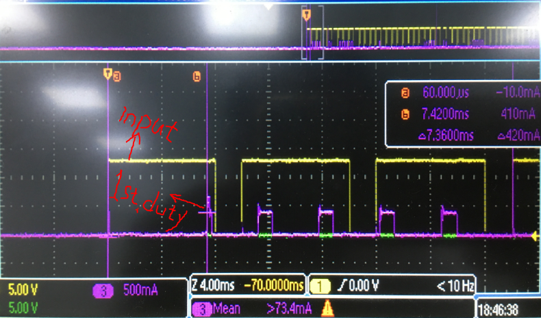
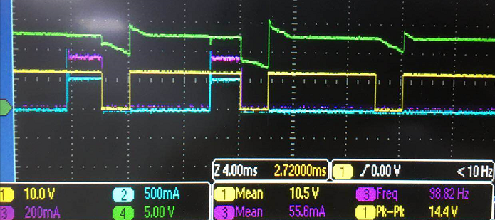
    Yes, I use the PWM dimming FET in my circuit, just similar to the buck-boost application circuit in datasheet. During testing, I found out it can start working successfully in the first duty cycle, and the start time is exactly as I set. However, it can not start to work correctly in the 2nd and following other duty cycles. It seems that the IC did not stop working after the input voltage falling to zero, so it can not start to work normally in the 2nd duty cycle. Please see screenshot below as reference. Is that I guess right? How can I do to let it start to work correctly in each duty cycle? Thanks. 

    For question No.2, I will adjust the parameters of input filter to have a try. Thanks .

    BR

    Han

  • Hi Han,

    The zero signal on your scope is the input voltage or is it the PWM signal?  If it's the input then look at VIN (pin 1) and VCC.  If VCC is dropping to UVLO then the part will turn off.

    Thanks Tuan

  • Hi Tuan,

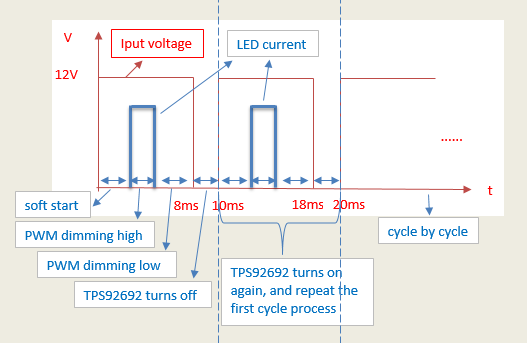
    The yellow wave in the picture is input voltage, and the purple wave is the input current of my circuit. You can see that input voltage turns on for 8ms and turns off for 2ms in every duty cycle. The start time I set is 7.36ms as shown in picture. I mean when input voltage falls to zero, the chip does not stop working immediately.

    So, you mean only when VCC drops to UVLO, then the chip will turn off immediately. Otherwise, part will continue to work for a short period, maybe more than 2ms, so it can't start correctly when next input voltage duty starts. Is that right? Further question, if VCC drops to UVLO, does PDRV(pin 12) turns to low voltage immediately? If not, I think it will make a big sense. Thanks a lot.

    BR

    Han

  • Han,

    Tuan is out of office for two days, and will respond when he returns on Tuesday US time.

    Thanks,

    Sumeet

  • Hi Sumeet,

    OK, thanks.

    Han

  • Hi Han,

    You have to look at the voltage VCC on the TPS92692 and not the input voltage for UVLO.  Please see section 8.3.1 of the data sheet again for this explanation on when the part goes into UVLO.

    In UVLO the dimming FET will be turned OFF.

    I am still confused about what you are trying to do here.  Please attach a copy of your schematic along with scope capture of the following on the same scope capture and what you expect it to do.

    Capture 1:  CH1:  VIN           CH2: VCC             CH3:  SS               CH4: PWM

    Capture 2:  CH1:  VIN           CH2: VCC             CH3:  PWM           CH4:  LED current

    Thanks Tuan

  • Hi Tuan,

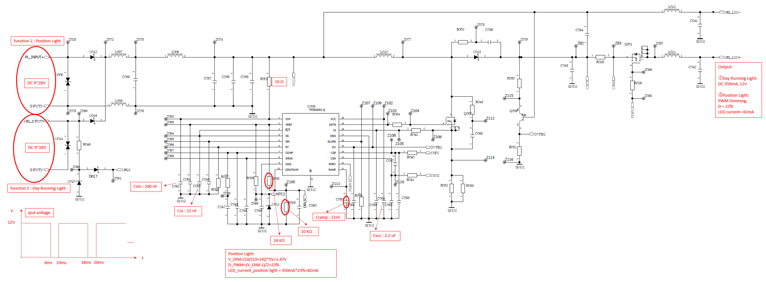
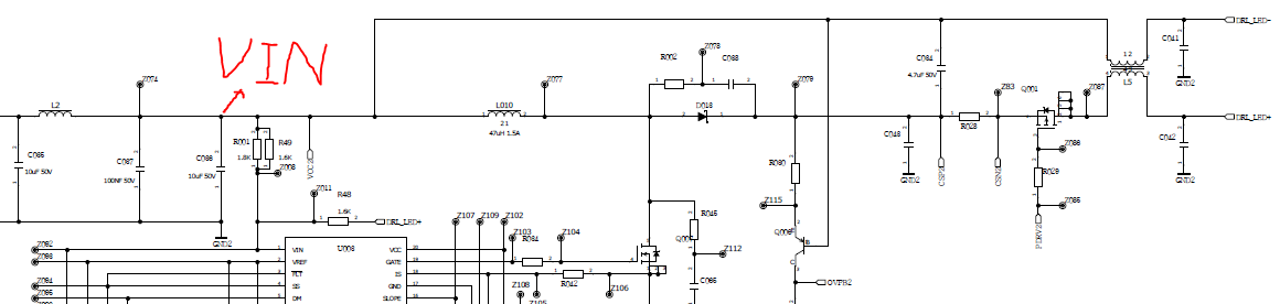
    Sorry for my bad description. I upload the schematic, please find it below. 

    There is a validation test for this circuit. That is, it should stay working normally when you add 'DC12V, f=100Hz, D=80% ' PWM voltage as input. However, it happens to flick when testing on position light. 

    Could you please help to make a check is there anything unreasonable in my schematic? Thanks. 

    Han

  • Hi,

    Any reply or anything unclear for my question?

    Thanks

  • Hi Han,

    From my post on the 17th...I am waiting for your scope captures on the following signals:

    Capture 1:  CH1:  VIN           CH2: VCC             CH3:  SS               CH4: PWM

    Capture 2:  CH1:  VIN           CH2: VCC             CH3:  PWM           CH4:  LED current

    Thanks Tuan

  • Hi Tuan,

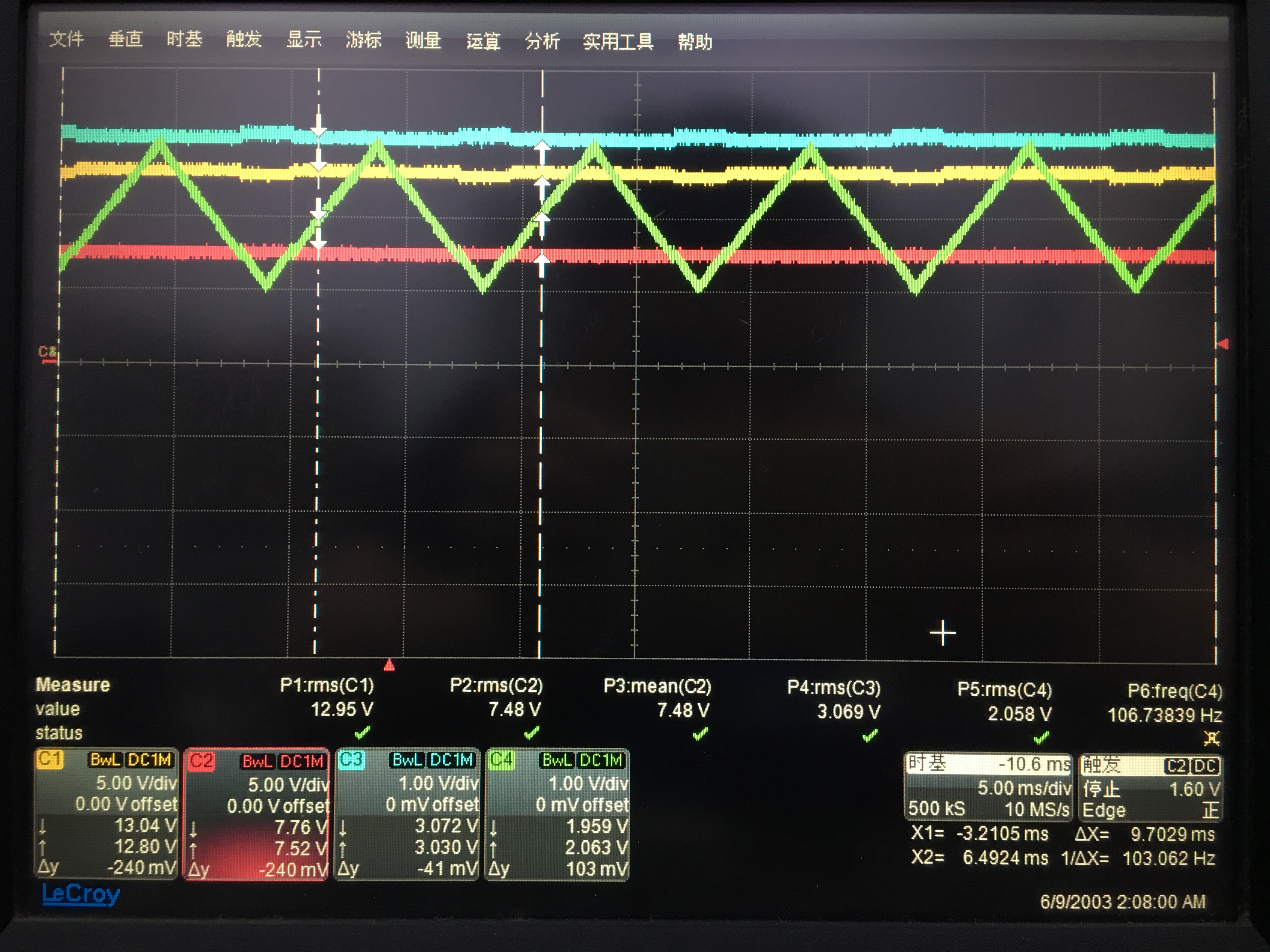
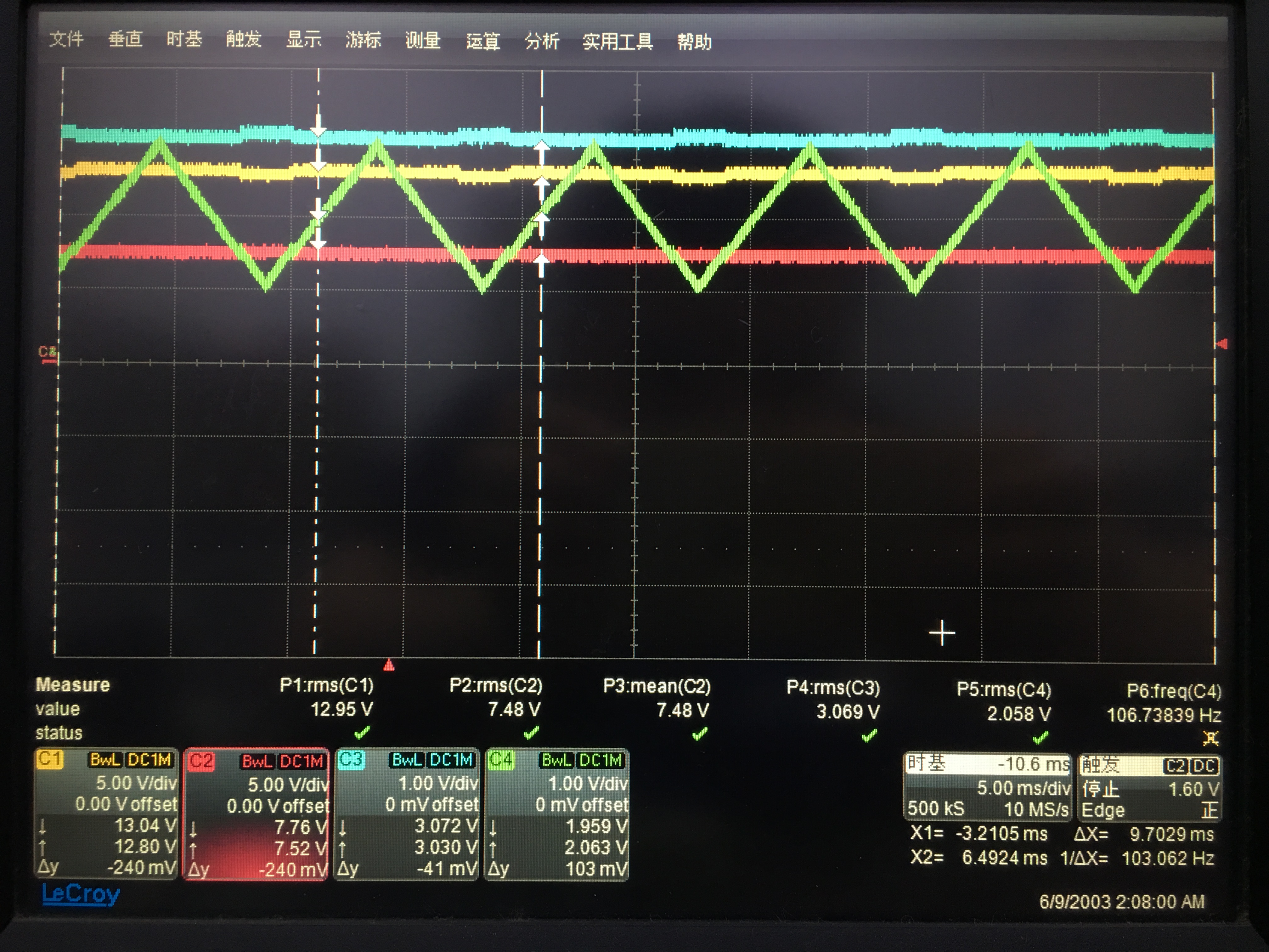
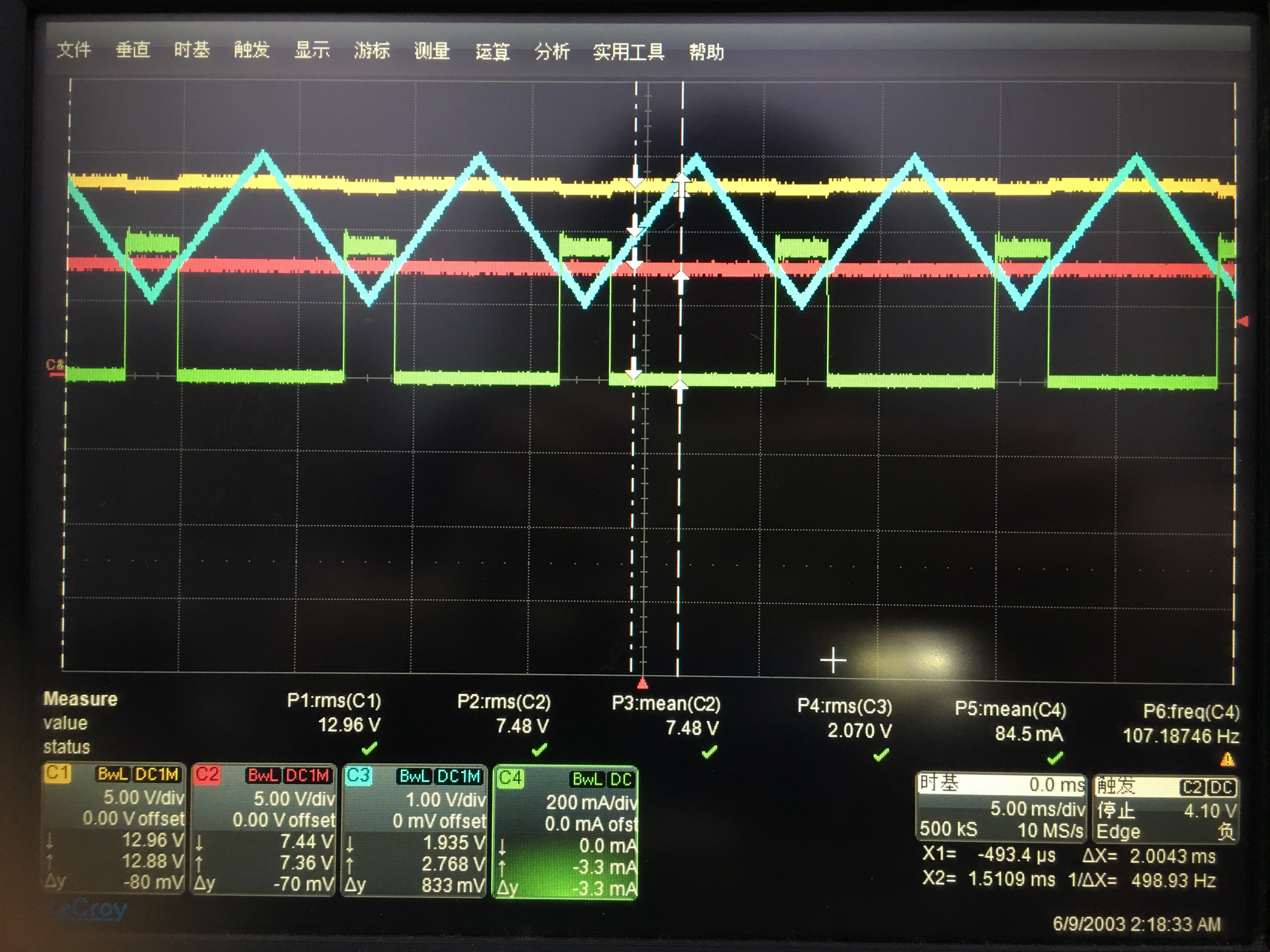
    Sorry for my misunderstanding. Here attached the scope captures:

    Capture 1:  CH1:  VIN           CH2: VCC             CH3:  SS               CH4: PWM

    Capture 2:  CH1:  VIN           CH2: VCC             CH3:  PWM           CH4:  LED current

  • Hi Tuan,

    Sorry for my misunderstanding. Here attached the scope captures. ( input voltage is 13.2V )

    Capture 1:  CH1:  VIN           CH2: VCC             CH3:  SS               CH4: PWM

    Capture 2:  CH1:  VIN           CH2: VCC             CH3:  PWM           CH4:  LED current

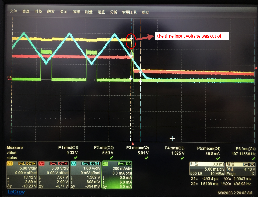
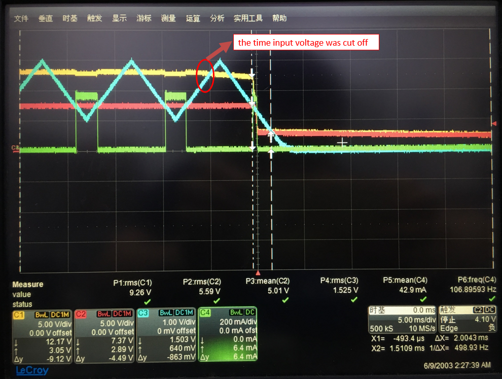
    Besides, I took another 2 scope captures below. They both are transient status when  input voltage was cut off. What I feel confused is why it can come out these two different results. 

    Thanks. Han

  • Hi Han,

    The scope capture you show me has the PWM dimming working and PWM'ing properly from what I can tell.  You are not showing me when it's not working.

    If input is cut off when PWM dimming is low then there is no power drawn from the input cap so the voltage does not droop you need to understand that as long as input voltage on VCC is above the UVLO then the part will continue to work.  Note that it's VCC and not VIN.  Please see UVLO section 8.3.1 of the specification.  From the specification VCC has to be minimum of 4.1V and the part will work.

    As far as the super impose voltage onto the DC input...I've mentioned this in my first reply in that this is a system level design and you have to either reject the input variation with the loop or the input filter.

    Please give mi scope capture when it fails then I can comment of why it's failing.

    Thanks Tuan

  • Hi Tuan,

    Sorry for some instrument limited, it's not easy to get the scope capture when it fails. 

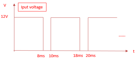
    For my question, in other words, is it possible for TPS92692-Q1 to achieve the PWM dimming function when I use the following voltage wave form as input voltage ?

    Thanks 

    Han

  • Hi Han,

    If the input voltage goes to 0V then the TPS92692 will turn off since it has no input voltage.  When Vin goes to 12V it will turn on and go thru a Soft-Start cycle first so it cannot perform your normal PWM dimming.

    Thanks Tuan

  • Hi Tuan,

    Since it works as you said, it cannot perform normal PWM dimming. Fully agree with you. However, my product is a light, as you know, we human eyes cannot feel flicking when PWM dimming frequency is above 100Hz. We can define this kind of work mode to a normal status. What I want is to reach this goal. Is it possible for TPS92692 to achieve this result when it works in PWM dimming ?

    Thanks

    Han

  • Hi Han,

    I've replied to you that if the input voltage to the TPS92692 (VIN) is going to ground as you have the input voltage shown in your post...It will not work as you want.  So the answer again is NO it will not work as you intended.

    Thanks Tuan

  • Hi Tuan,

    Thanks for your patience. I think I have understood your meaning. But maybe what I explained is not clear. Please refer to the following post. And, is it still not possible to achieve this kind of work status ? and why ? Hopefully get your help. Many thanks.

    Han

  • Hi Han,

    There can still be issue with what you are trying to do if you use internal PWM'ing from the TPS92692 as shown with schematic from your previous post or even with external PWM'ing.  The reason is the loop is disabled when PWM input is low and we tri-state the COMP and disable the driver...Please see section 8.3.10 of the data sheet. 

    If you use internal PWM as your schematic shown on the previous post then there will be an issue. 

    If you use external PWM then the timing has to be synchronized with the input voltage pulsing and with the understanding that the soft-start time is involve within the PWM high time and the LED current will start after the soft start time and LED current will go to ground when PWM pulse goes to 0.

    The other thing that you can do is use a diode into a hold up cap just for the TPS92692 VIN.  This is use to hold up the Vin of the TPS92692 so it's never in power off condition.  Then you would use external PWM that is synchronized with the input voltage pulsing.  The value of the cap will be larger than 10uF...Some testing needs to determine this value so that VIN does not go to UVLO during the 2mS where Vin is dropped to ground.

    Thanks Tuan

  • Hi Tuan,

    Thanks for your information. I do a lot of experiment on this issue. However, it still does not work. 

    I find out the only way to achieve the test is to make the PWM dimming synchronized with the input voltage pulsing under my previous schematic. Just as you said. But it's not possible to reach this goal for the dispersion of components and different batteries from application side. Meanwhile, it's quite difficult for me to change the schematic a lot for the very limited space of the product.

    Besides above mentioned method, do you have any other IC or solutions for recommendation to achieve the test ? Many thanks.

    Thanks. Han

  • Hi Han,

    The fundamental is when you want to PWM the LED on there HAS to be voltage on VIN for you to have energy to use.  If No VIN then no energy to drive the LED no matter what IC you use.  As I mentioned above you can do hold up caps to store energy so that the input voltage does not go to zero and that is the only way.

    Thanks Tuan

  • Hi Tuan,

    The VIN you mean is about the voltage on input cap or about the voltage on VIN pin of TPS92692 ? Thanks.

    BR Han

  • Hi Han,

    Voltage on the input cap...If there is no voltage then there is no energy for you to drive the LED. 

    Tuan

  • Hi Tuan,

    I put a diode in series to the input cap, and enlarge the value of the cap even to 50uF or larger, there is still a droop on VIN, so it still does not work.

    It seems that the diode can not stop the input cap from losing energy. There is still no energy for me to drive the LED when PWM input drop to ground.

    CHI: PWM input voltage, CH2: input current, CH3: LED current, CH4: VIN

    Thanks 

    Han

  • Han,

    Is VIN on your scope capture above the input to your board or is it the input voltage to the TPS92692 and the power stage?  Please give me a schematic on what you did with the signal labeled properly.  The fundamental is that if you have enough capacitance to hold up the input voltage to the TPS92692 and the power stage then it will work.  If your voltage is dropping to shut down the TPS92692 then you do not have enough capacitance or your supply cannot supply enough current to the hold up cap.

    Thanks Tuan

  • Hi Tuan,

    It's the voltage on input cap. You can see it as following. I just put part of the schematic because the other part is remained same as I put before. If I have enough cap to hold up the VIN to TPS92692 and the power stage, then PWM dimming will work normally even when PWM input goes to ground during the 2ms. Is that right ?

    Thanks Han

  • Han,

    Where is the hold up diode?

    Thanks Tuan

  • Hi Tuan,

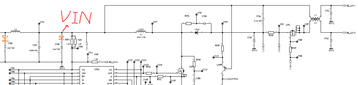
    I put 2 diodes in the position as I draw below. Please see it.

    Thanks Han

  • Han,

    You have the diode in the wrong place.  I was hoping you would understand a little better.  Please have the anode of the diode tied to the input from your supply and cathode to the L2 inductor and you can increase C66 or C67 (input caps) as necessary to be sure that Vin to the TPS92692 (pin1) never drops below 6V.  When the input voltage drops to ground the diode will reverse bias and the hold up caps (C66 and C67) will provide the energy to the TPS92692 and also the power stage.

    0268.e2e.docx