A related question is a question created from another question. When the related question is created, it will be automatically linked to the original question.
If you have a related question, please click the "Ask a related question" button in the top right corner. The newly created question will be automatically linked to this question.
[FAQ] UCC21520: What do I need to know about Bootstrap Overcharge when designing a driver bootstrap supply?
In a bootstrap supply, overcharge occurs when the voltage across the bootstrap capacitor (CBoot) rises above the source voltage for the bootstrap circuit (VBoot). This overcharge is generally a result of switch node undershoot.
Switch node undershoot occurs when the load continues to draw current as the high-side FET turns off, forcing current through the freewheeling diode of the low-side FET, which induces a negative voltage. An example of this switch node undershoot is shown in Fig. 1.
Figure 1: Example of Switch Node Undershoot Simulated with SiC Mosfets, VBoot=18V, CBoot = 2.2uF, RBoot = 2.2Ohm, Frequency = 200 kHz, duty cycle = 50%, dead time = 200ns
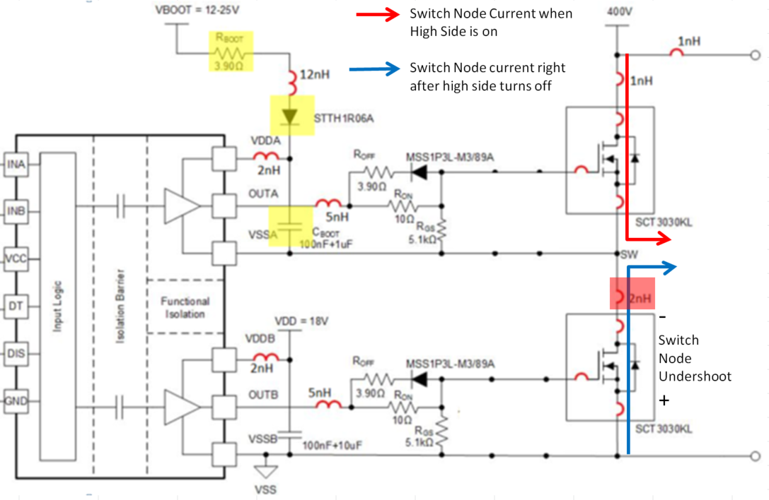
In this figure there are three components of undershoot that need to be understood. The first is shown the portion highlighted red. This segment, a large negative spike, is caused by parasitic inductance at the switch node (The inductor highlighted red in Fig. 2). The second component, seen in the two yellow highlighted regions in Fig. 1, is caused by the reverse current through the low-side FET (the blue arrow in Fig. 2) during the dead time of the driver, when neither switch is on. The magnitude of this component is determined by the characteristics of the FET and the load current. Finally, the green region on the plot is the minimal undershoot, which is dependent on the type of FET used. With these components of undershoot in mind, it is seen that reducing the dead time will reduce the second component of undershoot, which will decrease the overall effect of switch node undershoot, decreasing the bootstrap capacitor overcharge.
Figure 2: Typical Bootstrap Schematic
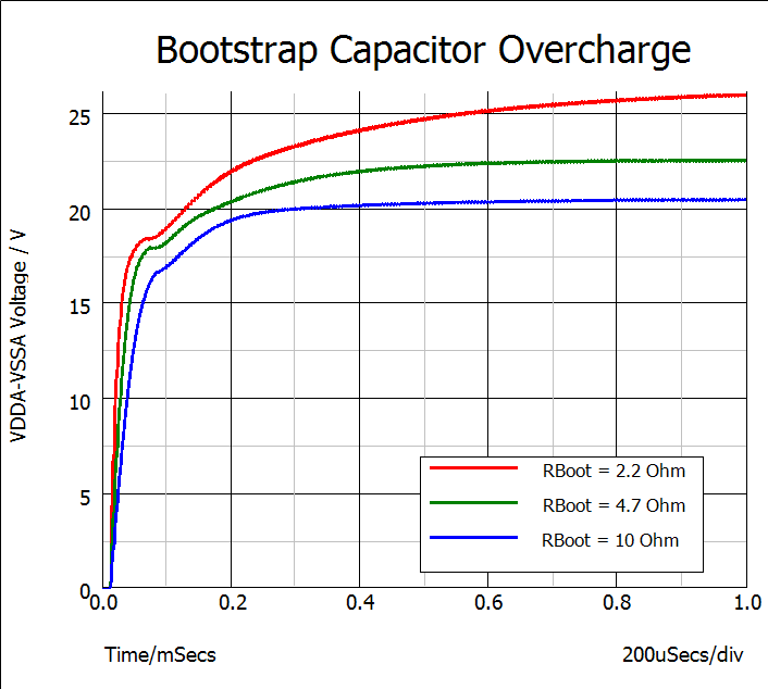
With this background, steps to correct bootstrap capacitor overcharge include first optimizing the dead time to reduce switch node undershoot. Beyond this, switch node undershoot cannot really be controlled, so its effects on overcharge need to be mitigated by increasing the bootstrap resistance and capacitance. Fig. 3 demonstrates the effect on bootstrap resistance on overcharge, with the peak voltage decreasing as RBoot increases. As is seen with the red curve, too small a resistance can allow CBoot to charge beyond the recommended maximum voltage.Bootstrap capacitance has a similar effect, with the overcharge decreasing as capacitance increases.
Figure 3: Bootstrap Capacitor Overcharge Simulated with SiC Mosfets, VBoot=18V, CBoot = 2.2uF, Frequency = 200 kHz, dead time = 200ns
If you are still having trouble with overcharge after implementing these suggestions or have further questions, please click the yellow “Ask A Related Question” button and we would be happy to help you.