This thread has been locked.

If you have a related question, please click the "Ask a related question" button in the top right corner. The newly created question will be automatically linked to this question.

LMZ31506: Possibly Hiccup LMZ31506 ?

Part Number: LMZ31506

Hi,

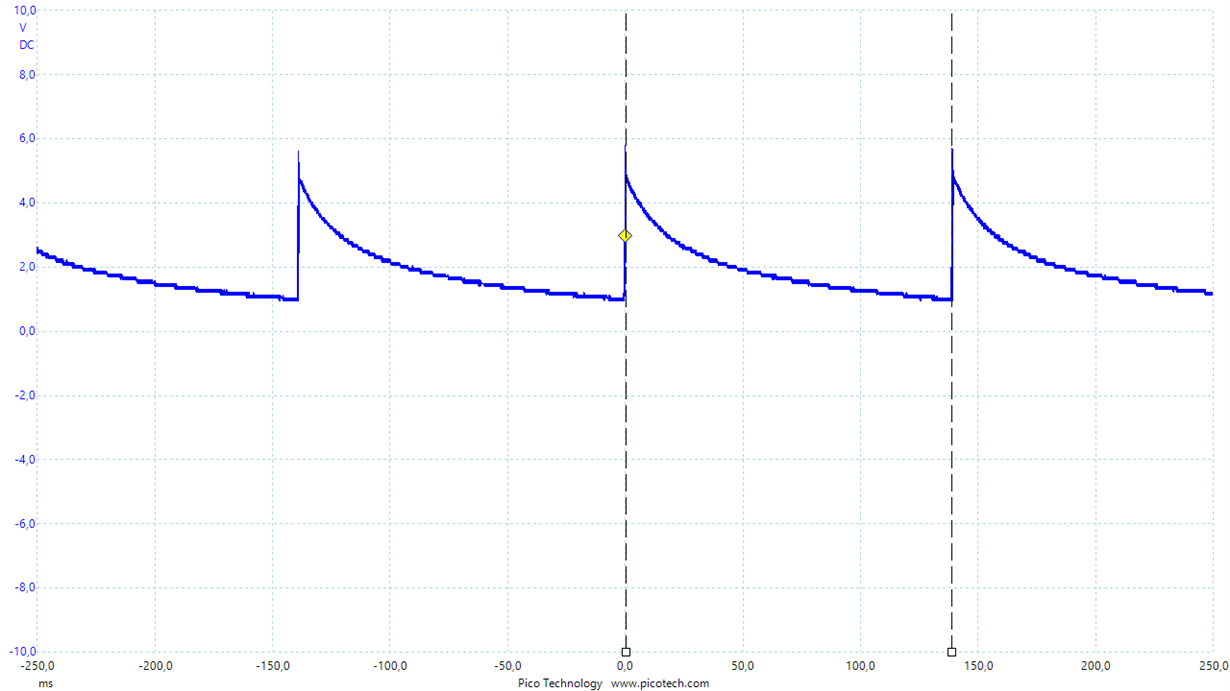
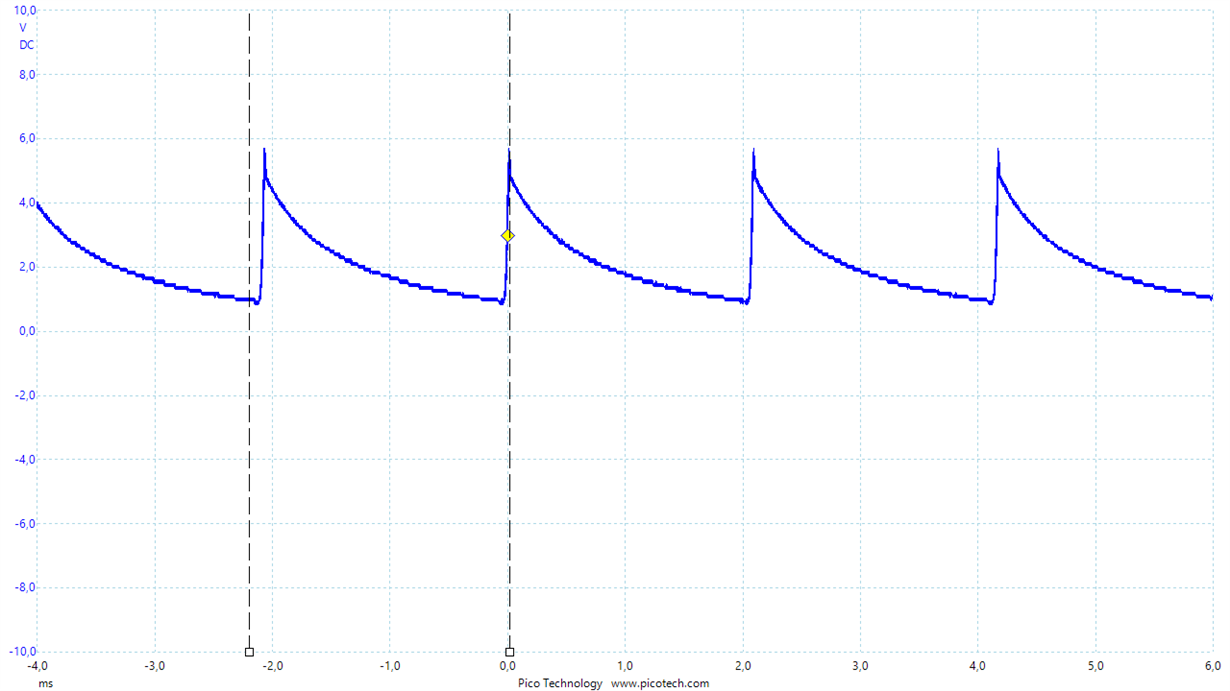
I have built a PCB where a LMZ31506 powers the circuit. The schematic and the layout I found in the datasheet. Inputvoltage is 12V and outputvoltage is 5 V. After applying power to the PCB the outputvoltage of the LMZ31506 goes up and down with a frequency depending on the load. (see attached pictures). I checked the pins of the IC on shorts

Is this behaviour hiccup ?

Could you help me please ?

Kind regards

Pierre

  •  

    What Schematic from the datasheet did your use from the datasheet?

    Can you share your schematic?

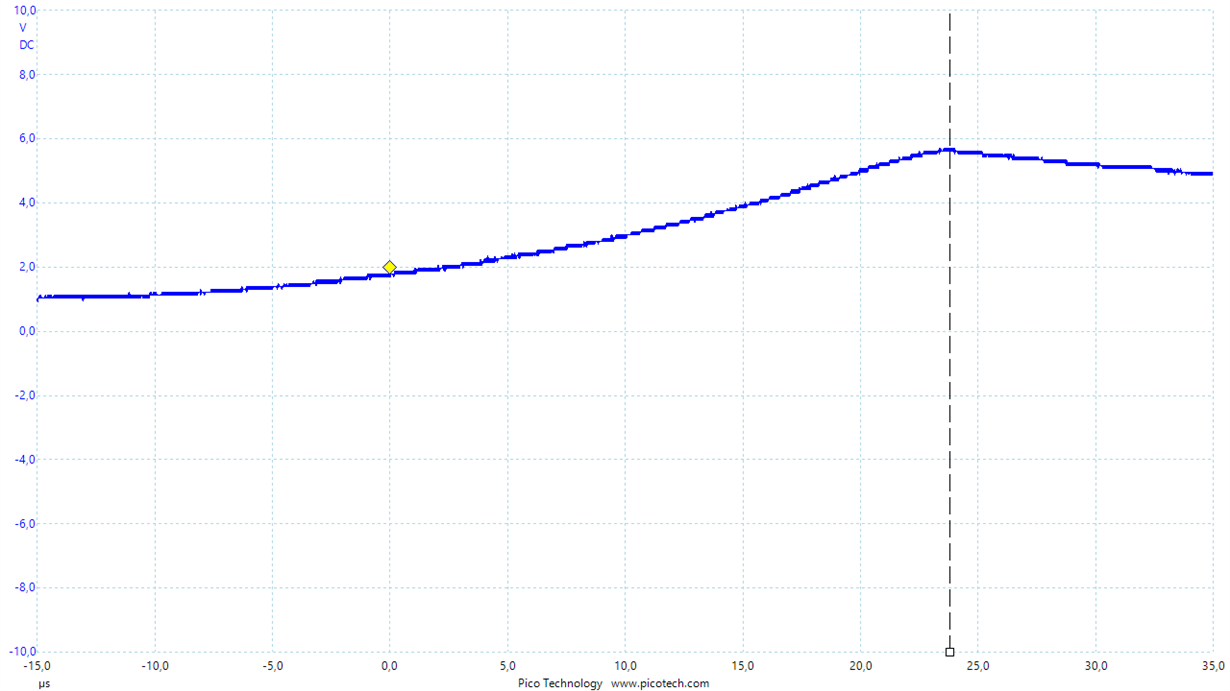
    Can you share an oscilloscope waveform that shows just 1 rise time of the output voltage so we an see the rise rate and the peak output voltage?

    How is the SS/TRK pin connected?

    The variation in repeating pulses from 140ms to 2.2ms seems odd, though the discharge seems to be following a resistive discharge, and the peaks look like they are excessing your 5V regulation target.

  • Hi Peter,

    I used the schematic in datasheet conforming to Fig. 23 and adjusted the following values:

    Vin = 12V, Vout = 5V Cout1=100uF, Cout2=0, Rrt=68,1K(by accident), Rset =196 ohm. I left the ss/TRK pin open.I connected the two undervoltage pins and set  the undervoltage lockout  to 9V according table 8 of the datasheet.

    The waveform shows the output voltage. At the cursor it has the topvalue of 5,7 Volt.

    Kind regards

    Pierre

  • Hi Pierre,

    This does not look like hiccup as the period varies with load. With the output coming up to 5.7V it seems like there could be an assembly issue but I see you may have already checked that.

    Does this behavior occur on multiple boards? Can you check to make sure the input voltage and the EN pin voltage is stable?

    The ramp up time on the output voltage also doesn't make sense as the internally set SS time is 1.1 ms. Is there something else connected to the output that might be overdriving the LMZ31506 output?

  • Hi Anthony,

    This is my first board. I checked the input voltage. There is a dip from 12V to 11,5V. This shouldn't be a problem, because I set set  the undervoltage lockout  to 9V . The output is unconnected at the moment because I assembled the board in parts.

    The Rrt resistor should be 86,6Kohm, but by a mistake I assembled 68,1Kohm. According to a simulation with the Pspice model of  TI this would not cause any problem, but in the WEBENCH there are  Recommended Limits for Rrt 82.08 kΩ - 92.55 kΩ.

    Kind regards

    Pierre

  • Hi Pierre,

    I agree, the different RT resistor values should not cause this problem.

    I have not seen this part family behave like this before so I am want to make sure there wasn't a schematic or layout mistake that was overlooked. Can you share an image of your schematic and layout of your board?

    Is it possible excessive heat was applied to the module during soldering causing the soldering for the internal components to reflow and become unconnected?

  • Hello Anthony,

    After your suggestion of excessive heat, I thought that the device was defect, so in a last try, I heated the complete device. Afterwards I tested the device and it works! The device delivers gives 4,99V.

    So something was wrong with the soldering. Maybe one of the three terminals under the device was not soldered.

    My problem is solved. Thank you very much for your suggestions and time.

    Kind regards

    Pierre