This thread has been locked.

If you have a related question, please click the "Ask a related question" button in the top right corner. The newly created question will be automatically linked to this question.

TPS546C23EVM2-746: TPS546C23EVM2-746

Part Number: TPS546C23EVM2-746
Other Parts Discussed in Thread: TPS546C23

Hi can anyone please help me by providing how to program the TPS546C23EVM2-746 in 2 phase mode to generate a 0.85 V with a 40A in TI Fusion. The default value is 1.2 V 70A in the evaluation board. Kindly respond

  • Hi,

       You can refer to the instructions in the EVM user guide. Please note that the EVM has feedback resistors of 10k for Rfbtop and 10k for Rftbottom.

    So you will have to consider that when you set Vout.

    https://www.ti.com/lit/ug/sluubh5/sluubh5.pdf

    Regards,

    Gerold

  •  

    If you just want to change the output voltage from 1.2V to 0.85V through PMBus without making any external resistor changes, I would recommend:

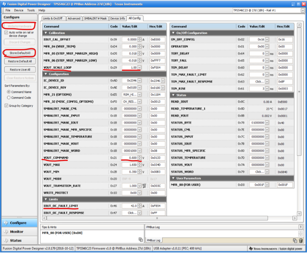
    1) In FUSION, select the "CONFIG" page

    2) Under Config, select the "ALL CONFIG" tab to bring up all of the available PMBus commands

    3) Change VOUT_SCALE_LOOP from 1.0 to 0.5 to match the external 10k and 10k resistors

    That will align the VOUT_SCALE_LOOP PMBus value with the external resistor divider so VOUT will track VOUT_COMMAND.

    4) Change VOUT_COMMAND to 0.85V

    Combined with changing VOUT_SCALE_LOOP, this will change the reference voltage to 0.425V so that the output voltage is 0.85V with the external 10k dividers.

    5) If you want to reduce the current limit for the 40A output, you will need to change IOUT_OC_WARN_LIMIT then IOUT_OC_FAULT_LIMIT.  For a 40A load current, I would recommend setting each phase to a current limit of 26-30A.

    6) Write those values to the Hardware, and if you want them to hold through the next power cycle, select "STORE to NVM"

    7) Since the TPS546C23 has separate PMBus addresses for each device, you will need to update the IOUT_OC_WARN_LIMIT and IOUT_OC_FAULT_LIMIT for the second devices as well.

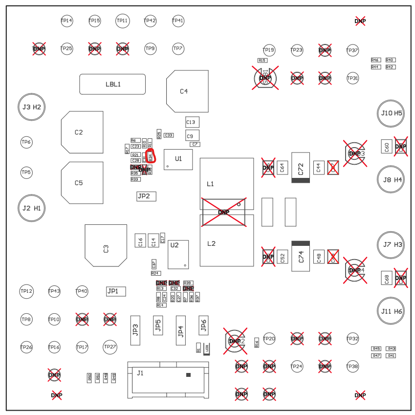
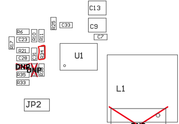
    If you are willing to change resistors first, you can remove R34, which will change the default output to 0.6V and the VOUT_SCALE_LOOP to 1.0, then you can skip step 3 in the above instructions.  With the external resistor divider, the output voltage regulation will be a little more accurate.

    The screen shot for "ALL CONFIG" is figure 33 on page 40 of the user's guide.  I have marked the commands referenced above, except IOUT_OC_WARN_LIMIT, which is directly below IOUT_OC_FAULT_RESPONSE, but you may need to scroll the right-hand scroll bar to see it.

    And the location of R34