This thread has been locked.

If you have a related question, please click the "Ask a related question" button in the top right corner. The newly created question will be automatically linked to this question.

TPS65216: Fails to power on with AC_DET tied high and PB pulsed low

Part Number: TPS65216

I'm building a simple AM335x-based system using the TPS65216D0 powered from an external 5V source, but it's failing to power on.

I had planned on having the system power on immediately (since it's not a battery-operated device), so I tied AC_DET high (since the datasheet says "Tie pin to IN_BIAS if not used") — only to realize later on that I actually want to tie the pin to GND to get the system to power up immediately. I'll fix this bug on the next release, but I'm trying to get this board working now.

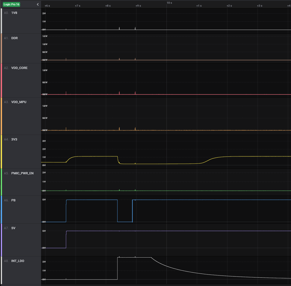
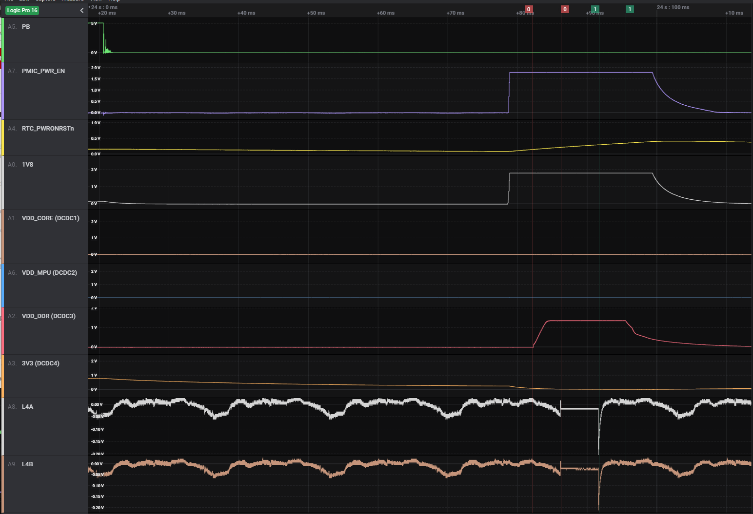
Luckily, I had the PB signal broken out and pulled up to 5V, so I attempted to power it on by shorting the signal to GND. When I do that, I see that INT_LDO rises to 2.5V (as it's supposed to do), but when I release the PB signal, INT_LDO goes back to GND and none of the other rails come up. I've tried touching the PB signal to GND for ~1 second, as well as for ~10 seconds.

I have PWR_EN connected to my processor, but I don't have a good place to probe it or drive it.

Any suggestions for next steps?

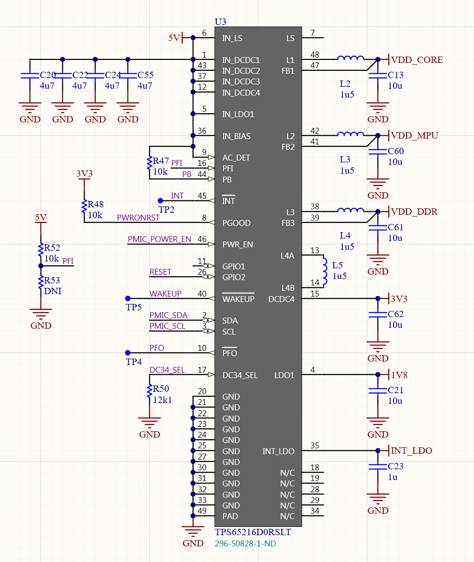
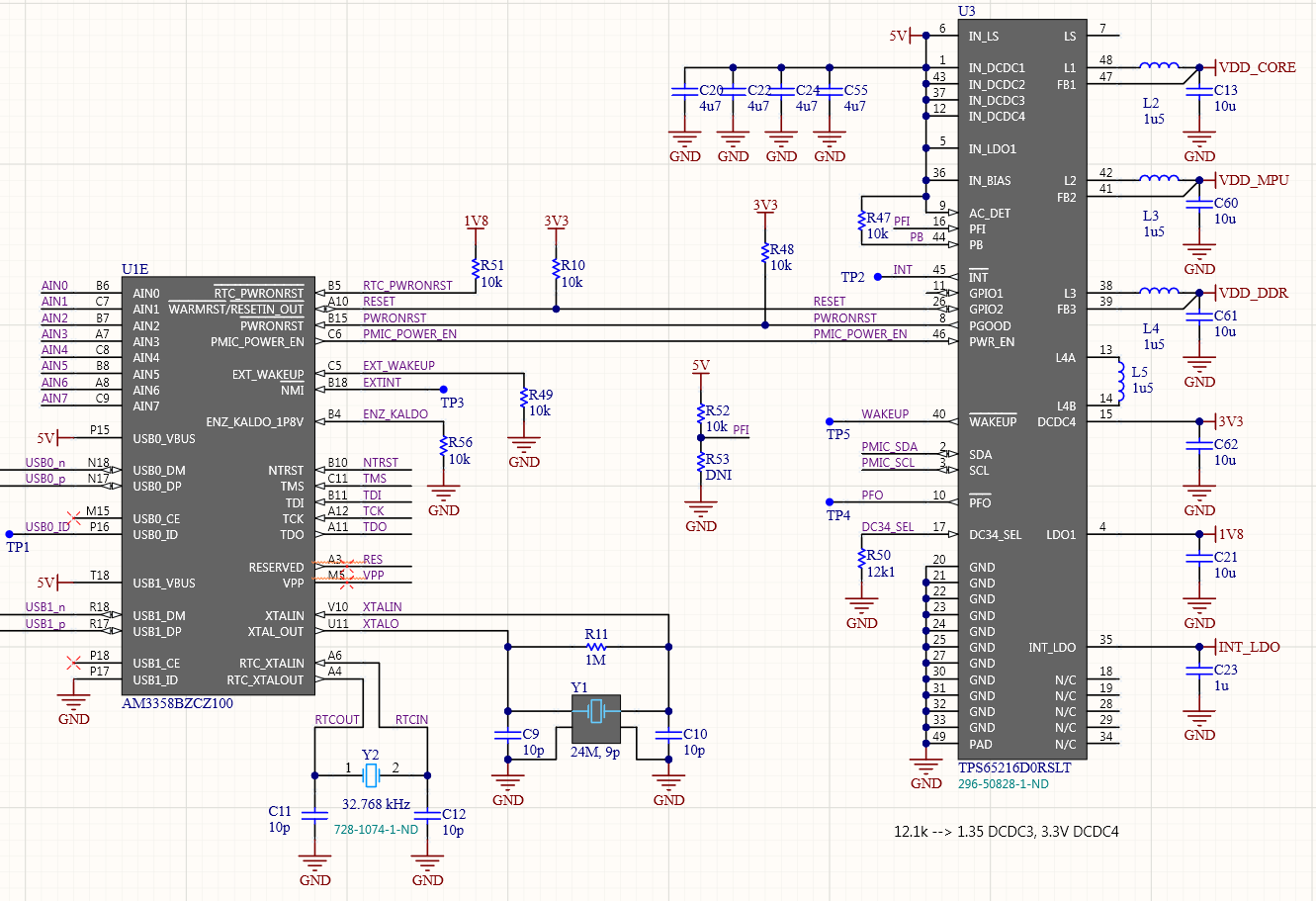
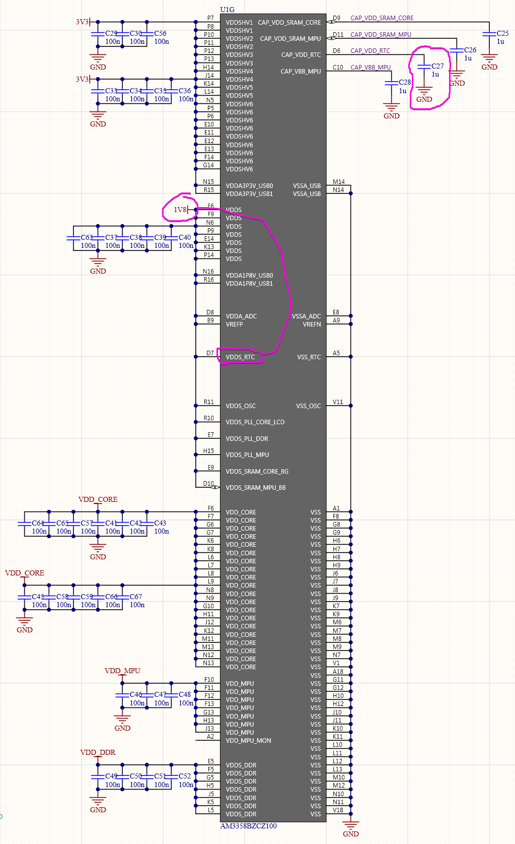
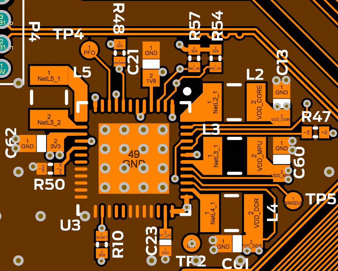
Here's my schematic:

  • Hi Jay,

    I assigned this thread to the responsible engineer late in the day and you should expect to receive a response from them by the end of the day tomorrow.

    Best regards,

    Layne J

  • First of all, I really like the color scheme of your schematic symbol in Altium :-)

    When AC_DET = IN_BIAS = VSYS, the PMIC is waiting for a push-button press to turn on. A push-button press is defined as a Hi-Lo-Hi event on the PB pin where the low pulse lasts for >50ms (deglitch timer). You do not need to hold PB pin low, nor is it advisable. After 8 seconds, the PMIC will reset if PB is stuck low.

    My concern is that PWR_EN might get set high by the processor (>10ms deglitch) but then return to a low voltage, due to the RTC domain of the processor not receiving power correctly.

    If you refer to Figure 5. Power Rails for RTC Domain on page 10 of the Powering AMIC110, AMIC120, AM335x, and AM437x with TPS65216 User's Guide, could you please confirm that this portion of your schematic is wired correctly?

  • Thanks! I hate the default "Altium Yellow" color.

    Other than a missing the RC delay capacitor on the reset pin, I think my connections match. If you want to double-check, I rearranged my schematic to show the connections with the AM335x:

    I used a Saleae to capture the 5V input, the 4 DC/DC + 1 LDO rails, along with the PB and PMIC_PWR_EN signal. It doesn't look like PWR_EN is ever going high:

    It looks like the supply is attempting to start? There's small glitches on the rails. Is that anything? By the way, DCDC4 (3V3) floats up to ~1.1V, but it's not actively being driven there — if I put a 10-ohm load on it, it immediately drops.

    Any ideas of next steps?

  • First of all, I do not see VDDS_RTC or CAP_VDD_RTC anywhere on the larger schematic image you shared. Seeing that these are wired correctly would be helpful. Also, it looks like you are missing the capacitor on the RTC_PWRONRSTn pin (which you mentioned above). This may be more important than you or I would expect, because that RC delay gives the 1.8V LDO1 rail enough time to turn on before the RTC domain of the AM335x processor is let out of Reset.

    The glitches are most certainly something. My guess would be that due to the timescale you are seeing them as short, low amplitude pulses, but in reality they are probably much more interesting up close.

    I would start by taking a look at 1V8 (LDO1). This is the first rail that tries to turn on in the sequence. If you zoom in and see that 1V8 still does not make it up to 1.8V then this is definitely an issue.

    But I also see the DCDC4 voltage floating up to 1.1V as an issue. Do you have another supply on the board somewhere? The AM335x rails are not fail-safe, so applying power at any pins other than USBx_VBUS before the PMIC turns on could present itself as a voltage on one or more of the PMIC rails.

    Finally, this is not common on the RSL package, but it is possible that the Thermal Pad is not physically soldered to GND. Sometimes, if you make your own symbol, this can happen, and the Thermal Pad is the only true GND for the device. The remaining pins labeled GND do not connect directly to GND inside the part, but tying them to GND minimizes leakage.

  • First of all, I discovered the 1.8V rail on the board I was testing is now shorted (that explains the short spike you were seeing). It wasn't initially this way, so I must have grazed it with the 5V rail while capturing data.

    Anyway, I built up another board, so we're back to the initial symptoms. But I've got some better-looking data now:

    Both the LDO1 (1.8V) and DCDC3 (1.35V) DDR rails come up in the correct order, but the sequencing stops there --- the DCDC4 (3.3V) supply never comes up. I probed both sides of the inductor and they're both flapping around in the breeze until DCDC4 tries to come up 4 ms later. The inductors are both pulled to GND for 5.45 ms, then it appears that DCDC4 goes into a fault condition and starts sequencing down the other rails. Please note the Y-scale of the L4A and L4B signals in the above image is greatly exaggerated — the peak-to-peak voltage is actually only 50 mV

    So why is DCDC4 faulting?

    There's no short circuit on that rail. This was the same rail that was floating around up to 1V. You wondered if there was another regulator powering it: definitely no. This is a simple break-out board with no active components other than the TPS65216 and the AM335x. The only 5V connections on the board are to the PMIC and the USB_VBUS pins of the AM335x (P15 and T18). Since it floats up to 1V whenever 5V is applied, it's got to be leaking either through the TPS65216 or through these two AM335x pins.

    Here's the other stuff you requested

    When I was building up this board, I soldered a 1 uF cap from RTC_PWRONRSTn to GND, just to be sure. That obviously didn't fix anything, unfortunately.

    Power supply connections on the AM335x illustrating CAP_VDD_RTC and VDDS_RTC:

    Layout illustrating the thermal pad is connected to GND:

  • Problem solved! Apparently my board house pulled back the copper going to one of the inductor's pads:

    That's why the 3.3V DCDC4 rail was never coming up. I think they did this because my copper fill was touching — but not overlapping — the pad.

    Anyway, all the rails are powering up properly and I'm off to the races! Thanks for joining me on my adventure!

  • Brilliant! Excellent debug work. Thanks for your patience and understanding with the long list of questions, and many thanks for following up with the great photo showing the true root cause of the issue. Nice to have a happy ending and a clear-cut root cause every now and then :-)