This thread has been locked.

If you have a related question, please click the "Ask a related question" button in the top right corner. The newly created question will be automatically linked to this question.

TPS61178: Low efficiency and stability issues when trying to decrease switching frequency

Part Number: TPS61178

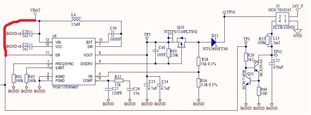
I'm writing to ask if you could help us with some technical difficulties that we have using TPS611781 boost converter. We use it to boost battery voltage from 2.7Vmin (triple NiMH AAA) to 19.5V.
    The first issue is that efficiency is much lower than we expected, based on design calculated by TI webench. As in the attached webench report, we expected 87.5% with Vin=2.7V, Vout=19V, Iout=50mA but according to out measurements we get only 74.5% with Vin=3.0V, Vout=19.7V, Iout=50mA. Better inductor didn't help much but lower frequency improves the result (84.5% is the best I got with frequency changed from 444kHz to 208kHz and lower resistance inductor PA4343.153NLT). It looks like switching losses are much higher than estimated by webench. Is this big error possible, or we do something wrong?
    The second problem is that after decreasing the frequency some stability issues appears. The main problem is with this bump in frequency response, about 40-50kHz - see the picture below. It increases when voltage is decreased (worst case is our design minimum 2.7V), it depends also from other factors (better if output capacitance is higher, temperature lower, frequency higher, inductance lower). When it gets too close to 0dB the converter starts oscillating (input current is sinusoidal). I wasn't able to change this frequency by changes of the circuits components, only the attenuation, but we'd like to fix the problem without need to increase output capacitance (space limitations), increase frequency (efficiency issue) or reducing inductance (high efficiency at 50mA which 33% of full load requires this inductance). This frequency didn't change also if NiMH battery with short wires was used instead of power supply and this bump was observed also in measurements with different switching frequency.
Have you got some hints about where this frequency can come from and how to deal with this issue?
Schematic in the attachment (inductor SRN6045TA-150, enable shorted to vbat, changes for tests with fsw=208kHz: R61=820k, C27=2n2, R32=5k1).

8524.WBDesign22.pdf


  • Hi Michal:

    We are out of office today. Please allow me reply next week. Thanks for your kind understanding.

  • Hi Michal:

    Thanks for your patience. 

    For the first question:

    The Webench is just giving a simulation value, and for your case, it seems the result is far away from the test result.I'm not sure if it mis-match the TPS611781 and TPS61178.

    We did a test before with Vo=16V/100mA, Vin=3V. the efficiency is 78%. May I know why you use TPS611781 but not TPS61178? As TPS61178 have the power save mode and better efficiency with light load. (87% for same case.)

    For the second question:

    I prefer to do analysis after checking if your really need the force PWM. 

  • I check evalboard modified acc. our circuit. There is no difference in efficiency. The IC marking is 15RI so I expected the PFM but there was no difference in frequency at different loads (from 0 to 150mA), always 460kHz.

  • Hi Michal:

    You mean you didn't see the PFM in our EVM with TPS61178(Which has mark 15RI)? Even there is no any load.

    May you share the waveform of the Vin, Vout, SW at such condition? 

  • I noticed that coupling between switched node and Rfreq can affect tendency to oscillate but even after cleaning up the layout in the evalboard the oscillations can happen at some conditions (especially if frequency is lowered to less than 340kHz, input voltage 2.8V, full load 150mA, connecting 1000uF capacitor with 2R3 resistance in series also made it worse). The main problem seems to be that loop gain is close to 0dB at ~40kHz, we couldn't find way to remove this gain bump. It's possible to partially attenuate it by reducing loop gain (e.g. connecting only ~50nF to compensation pin) but this causes triggering overvoltage protection when disconnecting load, so we'd like to avoid cutting the loop bandwidth.

  • Hi Michal:

    I'm out of office these days. Please allow me check the datails when I back. The target is 9 Oct. 

  • Hi

    Is there any progress?

  • Hi michal:

    Sorry that I missed this post. 

    What's the part number of your inductance? It seems the size is small, and I afraid if the ESR is large. And not sure if it has enough current capability. 

    If you have an current probe, it will be clear after checking the Icoil. 

  • It's SRN6045TA-150M (should be fine for the low output current). I tried much larger inductors with only very little effect on efficiency.

    Inductor current and SW voltage:

  • Hi Michal:

    According to the 0mA load waveform you shared before, it seems there is reverse current. May you share the waveform one more time with inductance current?

    And the output capacitor seems not enough, especially with DC derating considering.  (I found you mentioned 1000uF before, but I don't know where you put it.)

  • Unfortunately I can't check it now, anyway it seems to not be an issue, reverse current at 0mA load is what I'd expect in synchronous boost.

    While experimenting with the converter I tried a lot of changes, including adding bigger capacitors at input and/or output. Of course this didn't improve efficiency and improved stability only slightly (still there was tendency to oscillations at ~40kHz, especially with lower switching frequency).

    For now my findings are that:

    1. the efficiency at low input voltage is low because of switching losses and webench simulation provided highly inaccurate estimations

    2. the tendency to oscillate at ~40kHz when input voltage is low and frequency is low is a problem with the IC, this unexpected behavior is difficult to suppress by changes of components (including major changes of input/output capacitances, inductance, compensating components, changing source of power).

  • Hi Michal:

    If you use the TPS61178(PFM enalbe version), the reverse current should be a little. It has the zero current detection function, but maybe have a little delay.

    If you use the TPS611781, it make sense why the efficiency is low, especially for the light loading. 

  • Michal Stec said:

    1. the efficiency at low input voltage is low because of switching losses and webench simulation provided highly inaccurate estimations

    The efficiency given by WeBench is more reliable for normal case. For such low input voltage, there is a gap. We already note the simulation team, but it seems they need more effort.

    But in other side, as I mentioned, we did a test before with Vo=16V/100mA, Vin=3V. the efficiency is 78%. 

    Michal Stec said:

    2. the tendency to oscillate at ~40kHz when input voltage is low and frequency is low is a problem with the IC, this unexpected behavior is difficult to suppress by changes of components (including major changes of input/output capacitances, inductance, compensating components, changing source of power).

    I curious why you modify the EVM so much. Does it work in your side? I asking such question is because we used that for the test: Vo=16V/100mA, Vin=3V and it worked well. 
  • As mentioned, both PFM and no-PFM work the same for me.

    At 50mA load there is no reverse current, 0mA load behavior is probably not an issue.

    The result "Vo=16V/100mA, Vin=3V. the efficiency is 78%." seems close to what I've got, I have worse efficiency probably because of lower load (50mA) and higher voltages ratio.

    The evalboard works, it was modified because we can't have large components in our design.

    The problem with stability increased when I tried to reduce frequency  to get a little more efficiency. Closer to 200kHz it seems to be hard or impossible to get stable operation (I tried with larger capacitors too).

  • Hi Michal:

    The right plane zero is also a risk for your design, especially the inductance is so large and higher voltage ratio. I did an quick calculation, it's around 120kHz. And lower switching frequency will increase the loop stability. Both of them require a lower crossing frequency in Bode Plot.

    You can set the Fcross around 10k-20kHz to have a try, but the loop will be very slow. 

  • Hi Michal:

    As long time no hear from you, I assume you have solved the issue. If not, just reply below. Thank you!