This thread has been locked.

If you have a related question, please click the "Ask a related question" button in the top right corner. The newly created question will be automatically linked to this question.

BQ24072: Device seems to be entering USB100 mode when designed to operate in USB500 mode

Part Number: BQ24072

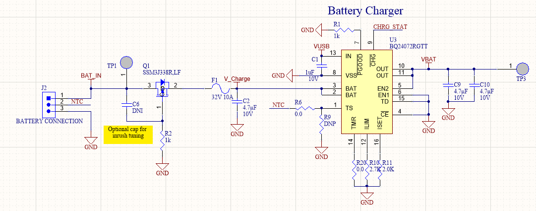
Our board is designed to keep the BQ24072RGTT in USB500 mode to allow charging of a LiPo battery when a USB cable is plugged in. We have seen 2 instances out of ~200 devices of this IC limiting the input current to 100mA. Both devices initially worked as designed and allowed for 500mA  input current to charge the battery, then they started limiting to 100mA input current. I see no issues with any of the input pin levels that would cause this USB100 mode.

  • Hi Eric,

    Welcome to E2E!

    Just to narrow down the issue, would you be able to share the schematic? Is this issue repeatable? If it is, would you be able to capture a waveform at the INpin for voltage at the time of this occurring? Can you also check the voltages at the ENx pins? 

  • Hey Anthony,

    The issue is repeatable. Once a board starts displaying the issue I have not found it to be recoverable.

    See below for the schematic of the BQ24072, as well as a screen capture showing the USB plug in. The EN1 pin is tied directly to a GND plan, and the EN2 pin is tied directly to the OUT node. 

    Thanks for the support,

    Eric

  • Hi Eric,

    Thanks for the waveform. Would you be able to pull EN2 low and EN1 high? This is the configuration that is used to put the device in USB500 mode. The schematic is fine overall as the way you have it, it's allow for about 550mA input max.

    Would you be able to measure the current at IN, BAT, and OUT?

  • Hey Anthony,

    I am unable to toggle EN1 due to the board layout. This pin is connected to ground underneath the IC package. I can toggle EN2 from low to high (OUT) with no change in charging current. 

    I am unable to measure the current at OUT due to the board layout, but currently the OUT pin is not connected to a load other than the filter caps shown in the schematic.
    Current at IN: 98mA
    Current at BAT: 94mA
    All the best,
    Eric
  • Hi Eric,

    Thanks for the information. What is the voltage at the TS and OUT pin? 

  • Hey Anthony,

    When the USB is unplugged, and the battery is powering the system, TS = 0V (GND), and OUT = 3.8V. Once the USB is plugged and and 100mA is flowing, TS goes to 0.69V and OUT goes to 3.95V. Any other items to investigate for this issue?

    All the best,
    Eric

  • Hi Eric,

    This could be DPPM issue. Due to the output voltage dropping possibly due to no load, the charge current is being reduced. Would you be able to try with a load?

  • Hey Anthony,

    I have tried with a 25 ohm load across Vout to GND and a 50 ohm load. For both conditions, the input current does not surpass 100mA.

    All the best,

    Eric

  • Hi Eric,

    Do you have waveforms and measurements for a board that is not displaying the issue?

    For DPPM, the device is seeing a drop in the output voltage and reducing the charging current to prevent the voltage dropping. This can be due to the input current not being able to supply the combined current for charging and the load which would lead to the output voltage decreasing. For the BQ24072, DPPM will occur once the output voltage drops below  the regulation voltage by 100mV. 

    Can you can reduce the charge current to see if this helps?

  • Hi Anthony,

    With the previous test, the supply current is more than enough to supply both the load and battery. I've tested with a good board as well and the battery charging current does not drop to this 100mA area, it stays near 500mA. 

    The device with the issue is not just reducing the charging current to 100mA, the total input current seems to be capped at 100mA, regardless of load, or battery charge. If I connect a load of 200mA, and remove the battery, the device still only allows 100mA input current.

    In what way should I reduce the charge current? Increasing Rilim? 

    All the best,

    Eric

  • Hi Eric,

    Thanks for confirming the current, doesn't seem like changing the charge current would be helpful just yet. Would you be able to provide waveform with all of the following voltages at the following pins: IN, OUT, BAT, and ISET. Also, would you be able to switch the IC from a board where you see the issue to a board where the issue isn't seen? 

  • Hey Anthony,

    See attached for waveforms from the failed board and from a good board.

    I cannot remove the IC easily as I don't have the appropriate equipment in house. For the first unit that displayed this failure, I had our CM replace the IC on the defective board. Once the IC was replaced, the defective board worked as designed, allowing 500mA charge current.

    All the best,

    Eric

    Failed Unit:

    Good Unit:

  • Hi Eric,

    Would you be able to try connecting the battery directly to the BAT pin instead of through the 10A fuse? Is there a concern for overcurrent?

  • Hey Anthony,

    The fuse is to have a redundant safety catch. 

    Connecting the battery directly to the BAT pin had no change to the system, still pulling only 100mA input current.

    Are there any additional items I should look at here? What are the next steps to root cause this issue? Is TI able to check for internal IC damage?

    All the best,

    Eric

  • Hi Eric,

    From the waveforms where the unit is not correctly operating at USB500 mode, is the input voltage dropping below the Vin-DPM threshold (typically 4.5V)? This could be potentially be our suspect. If the device is in either USB100 or USB500 mode, the input voltage is monitored and if it falls below the threshold, the input current is reduced. 

  • Hi Anthony,

    I'm sorry, I made a mistake in the title of this post. The device is not setup to run in USB500 mode. The device is setup with EB2=HIGH, EN1=LOW, to allow for R_ILIM to set the max input current. In this configuration I was under the impression the DPM Mode is not active. I have tested with multiple USB sources and the same issue persists across sources. 

    From the datasheet, the only items I see that would put the devices that have failed (up to 3 now) all into this 100mA input current bucket would be:

    Internal damage to EN2, indicating to the device to enter USB100 mode. (EN1=0, EN2=0 -> USB100 mode)

    Internal damage to the OUT voltage sensing, causing the device to get stuck in the logic block of checking for Vout Short (page 18 of datasheet).

    Any other items to check on these device? 

    All the best,
    Eric 

  • Hi Eric,

    Is the Battery connected to the output as mentioned in the schematic? As the board was working this wasn't a concern but if the EN2 pin is connected to the battery, this could be an issue of a misconfigured board if not damage. 

  • Hey Anthony,

    The battery is not connected to the OUT of the IC. The OUT is connected to a node called VBAT (a carry over from a previous design iteration). From the schematic, the battery connects at J2, through the fuse F1, and connects to the BAT pins of the IC.

    EN2 is connected to the OUT pins of the IC, not the battery. I believe the schematic matches that provided on the BQ24072 datasheet. 

    What would be the next steps to understand the root cause of this issue? Is TI able to look at the IC itself to inspect for any internal damage? 

    All the best,
    Eric

  • Hi Eric,

    Thanks for the confirmation, I will email you offline regarding the next steps and close this thread. 

  • Hi Eric,

    I've sent you information via email in regards to the next steps for return and I will close this thread. We can continue communication through email.