This thread has been locked.

If you have a related question, please click the "Ask a related question" button in the top right corner. The newly created question will be automatically linked to this question.

LM5176: Using LM5176 as Battery Charger it happens that there is an unwanted reverse current flow

Part Number: LM5176
Other Parts Discussed in Thread: LM5175, PMP10594, TLV272, INA180

Dear Sirs,

I have a big problem discovered only now with my Battery charger circuit that use LM5176.

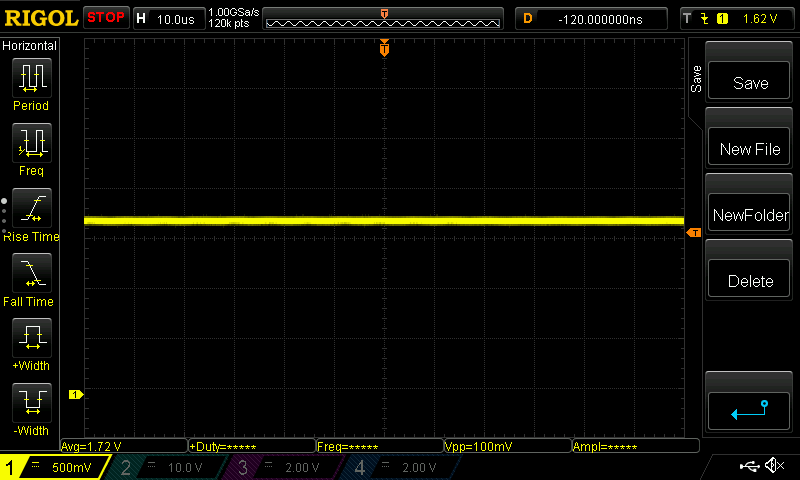
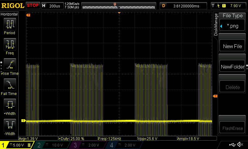
When battery is fully charged and I'm maintaining the max voltage at the end of the charge (for example 14.4V), I have a strange and unexpected reverse current flow between the output battery and the input source supply, in fact the input voltage of my power supply increase form 12.5V that is my standard value to 25V!!!! So during the charge my circuit works mainly in BOOST region.

My schematich is a standard one, with output average current limit shunt resistor and 93.1K resistor on MODE pin.

How can I prevent this phenomenon?  Is it possible use the LM5176 in CCM only during this step of charge?

Please I need some tips to solve this problem ASAP. 

Thank you for your time!

Best regards,

Francesco

  • Hello Francesco,

    If the battery voltage is somewhat higher than the regulation level of LM5176, it is possible that the device tries to regulate to the value it should have and deliver energy back to the input. Is there the possibility that the battery voltage increases above the maximum value you allow during CV regulation? If this is the case, CCM is not the right operation mode.

  • Dear Brigitte,

    I tested the battery charger with a not fully charged LiFePO4 battery, so after some minutes that it is under charge at constant current, it goes in constant voltage at 14.4V, this battery is connected only to the output of my charger and there aren't loads or other stuff that can charge it, only my charger board with LM5176. For this ragion I can't explain why I have a reverse current flow that increase the voltage on the output of my input source Power Supply from 12.5V to 25V.

    Consider that I have a resistor on the FB pin to set the wanted CV value, it is controlled by a PWM signal from the MCU right filtered as a DC signal.

    Are there some tips to prevent this behavior? 

    Thank you!

    Best regards,

    Francesco

  • Dear Brigitte,

    in the meanwhile I replaced the LM5176 with the LM5175, on the same board, I changed the RT resistor to have the same switching frequency and I used a 49.9K resistor on the MODE pin to work in DCM mode trying to solve the problem about the reverse current flow, but I encountered another main problem:

    The high side outptut mosfet have a gate voltage equal the source voltage (14.1V max), so it doesn't work as mosfet but works only the schottky diode in parallel. It is very strange because I have 25V (source voltage + 7.5V) at the pin  BOOT2 but only 14.1V max at the HDRV2 pin. It is a new just mounted LM5175, what can be the problem?

    Please I need to solve it urgently.

    Thank you in advance.

    Best regards,

    Francesco

  • Hello Francesco,

    LM5175 would have been my next recommendation. You mention that the HDRV2 is only working like a diode, so it is preventing current from flowing backwards. So why is there 25V on the source? I thought that the backward current causes the voltage to rise from 12.5V to 25V? What are you using as source?

    Would you please share your schematic? If you want to keep it private, please send me a friendship request.

  • Dear Brigitte,

    on LM5175 I'm using a Power Supply unit as source at 12.5V, in the output I have the expected voltage, but if I put a Load, I can see that the Gate signal on the Boost Top Fet, is equal the source signal, so it works as a diode, and I have not current flow back, but efficiency is very low, why these mosfet are not switched?

    I read on the forum that this can be affected by the inductance of the shunt resistors on pins CS and CSG, so I tryed to change the filter capacitor mounted near these pins but increasing the R-C I don't see any improvements, Have you any suggestion?

    As check I replaced the 49.9K on the MODE pin with a 93.1K and the gate signla on the Boost Top Fet is good higher respect the source signal, this is the proof that the HW is ok and the shunt resistor inductance should be a probable cause.

    Please can you give me some method to compensate this problem?

    Thank you!

    BR

    Francesco  

  • Hello Francesco,

    The device turns off the HDRV2 pin, when it detects zero current or negative current by checking the voltage drop between SW1 and VISNS.

    As the voltage on SW1 will be influenced by impedance on the sense resistor connected to GND, you need to minimize the impedance there. You could for example use a resistor that is shorter than wide to reduce inductance.

    Please check the inductance of the resistor you are currently using and try to find one that has lower inductance. On the EVM we are using a resistor from Susumu for example.

    Please share your schematic.

  • Dear Brigitte,

    I replaced my shunt resistors with another model for a test, but always the same behaviour. I shortcircuited the CS and CSG pins bu it do alway the same. I don't understand why!

    I used another board with the LM5176, I thought that If I put a small load on the output in parallel to the battery to charge, the reverse current flow phenomenon should disappear, because the DC-DC converter has always a current path from the input to the output, but testing this I noted that it is false, reverse current flow happen always when the battery voltage reach the setpoint for the output voltage and current absorbed frm the battery is near 0A.

    So, since I have many problems to get the LM5175 working in DCM, please have you any suggestion or an adding circuitry to prevent reverse current flow on LM5176? Consider that my DC-DC converter is a battery to battery charger with an output power of about 600W, so it is not possible add series diodes in the input/output.

    My question is if are ther some tricks to control the SS or COMP pin or others to prevent reverse current flow keeping as trigger the measue of the output or input current.or voltage?

    Please help me to find a fast solution!!

    I attached my schematic but please I wish to have your private e-mail for a Layout review!

    I measure the input and output current with N°2 INA186A1, and the I used OpAmp to control the COMP pin for input and output current limit like the PMP10594 demo board.

    Controller_and_Power_Stage.pdf

    BR,

    Francesco

  • Dear Brigitte,

    I replaced my shunt resistors with another model for a test, but always the same behaviour. I shortcircuited the CS and CSG pins bu it do alway the same. I don't understand why!

    I used another board with the LM5176, I thought that If I put a small load on the output in parallel to the battery to charge, the reverse current flow phenomenon should disappear, because the DC-DC converter has always a current path from the input to the output, but testing this I noted that it is false, reverse current flow happen always when the battery voltage reach the setpoint for the output voltage and current absorbed frm the battery is near 0A.

    So, since I have many problems to get the LM5175 working in DCM, please have you any suggestion or an adding circuitry to prevent reverse current flow on LM5176? Consider that my DC-DC converter is a battery to battery charger with an output power of about 600W, so it is not possible add series diodes in the input/output.

    My question is if are ther some tricks to control the SS or COMP pin or others to prevent reverse current flow keeping as trigger the measue of the output or input current.or voltage?

    Please help me to find a fast solution!!

    I attached my schematic but please I wish to have your private e-mail for a Layout review!

    I measure the input and output current with N°2 INA186A1, and the I used OpAmp to control the COMP pin for input and output current limit like the PMP10594 demo board.

    5468.Controller_and_Power_Stage.pdf

    BR,

    Francesco

  • Dear Brigitte,

    In meanwhile I tested the LM5176 with pin MODE fixed at GND, and I saw that like the LM5175 it works in DCM too!

    Is it possible to use the LM5176 in DCM mode?

    I'm waiting for your appreciate reply.

    Thank you,

    BR,

    Francesco

  • Hello Francesco,

    Fix MODE to GND is not allowed in LM5176. If you want to use DCM, then you need to use LM5175.

    If there are problems with the LM5175 in DCM, these are possibly related to the problems you encounter with LM5176. Normally the replacement should be simple and straight forward.

    Would you please share some measurements of VIN, VOUT, SW1 and SW2 and if possible the reverse current especially at the point when the device starts to send current back to the input?

    Your schematic is really hard to read, so I am not sure if I overlook something. Here are my comments:
    - Please remove the components between SLOPE and ADD_COMP.
    - Please remove the additional circuit on ISNS+/-
    - Why do you have such a lot capacitance on VCC?
    - You should increase the sense resistors to values which are closer to the needs of your application. To get a good starting point you could use the quickstart calculator on the LM5176 product folder.
    - Please check if the behavior changes when you remove the snubber resistors and capacitors on both switch nodes.

    For the layout, it would be very helpful to get screenshots of the placement and layers instead of gerbers.

  • Dear Brigitte,

    I added some circuit on SLOPE that add a capacitor on SLOPE pin only whane the circuit must work as BUCK converter, otherwise I have soe instability during the working input/output voltage range.

    The added cirtuit arount the ISNS+ and ISNS- I seen on some Application note and demo boards of the LM5176 it should improve the accuracy of the output Hardware Average current limit. If you think that it is not necessary, I can remove it! So I save cost too!

    I added more capacitors on VCC to be sure that it is stable, since my mosfet are very powerfull and the Gate capacitors are not very small. If you think that total capacitance is to high, please let me know what is the best value to use, so I reduce the mounted capacitors.

    About the sens resistors on the Power GND node, 1mOhm is the correct value for my application, but I tested also the same board with LM5175 and 3mOhm shunt value, but the gate TOP mosfet is not activated, the behavior is always the same.

    About the smubbers circuits theya are already not mounted.

    On my board the gate resistors are all 0Ohm.

    I sent you in pivate the screenshot of the 4 layers of my board for a layout review!

    Thank you in advance.

    BR,

    Francesco

  • Hello Francesco,

    When checking LM5175 in your design: Could you check if HDRV2 reacts differently with different input voltages? If you set the device in CCM, does then HDRV2 turn on as expected?

    Up to now, I did not find an obvious problem in the layout, but will need some more time to review it in detail.

  • Dear Brigitte,

    Yes I can confirm that if I put a 93.1k resistor on MODE pin, it works fine in CCM mode, so the HDRV2 pin works fine, the top boost mosfets are correctly driven.

    Studying my layout maybe a mistake that I done is that the tracks HDRV1 and SW1 and HDRV2 and SW2 should be routed as differential signals to reduce the loop area for the gate signals, but I can't believe that this can cause the continuous trigger of the comparator  on CS and CSG pins.

    I'm waiting for your appreciate reply or trick to solve my problem.

    Thank you in advance.

    BR,

    Francesco      

  • Hello Francesco,

    Do you think you could add a series resistor of 100 mohm between VISNS and the top transistor driven by HDRV1? I just wonder if HDRV2 is turning on properly if there is more voltage drop between these 2 pins.

  • Dear Brigitte,

    I don't know if I can add that resistor, but I'll try to do.

    In meanwhile I buoght other LM5175 ICs to replace on the First board, so I'll take oscilloscope screenshots to show you the requested signals on my board when setted in DCM mode.

    I Hope this will help us to find a solution.

    Thank you.

    BR,

    Francesco

  • Dear Brigitte,

    I added a series resistor between the VISNS and the top Buck mosfet drain, and I saw that the output top boost mosfet is correctly driven!!

    So you are right it depends on voltage between the VISNS and SW1, but please how I can get it working without a series resistor?

    Since my charger is an high power charger, adding a series resistor is not possible, so have you a trick to solve this problem? Can I add some external circuit to set the correct current treshold to do the diode simulation in the output?

    I see that if I put a small resistor (20mOhm in series) the output mosfet is driven correctly only if the input current is bigger than 10A, but for my application 20mOhm in series is too much, consider that on my board there are 3 shunt resistors in parallel of 2mOhm  mounted in series on the input voltage, to read the input current, to mimimize power loss, but they are not enough to get the LM5175 working at 5A, 10A, 20A.

    I'm waiting for your appreciate reply.

    BR,

    Francesco. 

  • Hello Francesco,

    Thank you very much for testing the converter with a series resistor between VISNS and the top transistor.

    The addition of the resistor should only help to identify the issue, not being used as solution for the issue you observe. It seems that due to any case the VISNS pin is seeing 200mV less than SW1. Now we need to identify where this is coming from.

    Could you please try to measure the voltage on the pins VISNS and SW1 after you removed the resistor? I hope that the measurement there helps in addition to identify the issue.

  • Dear Brigitte,

    I did the measurement removing the series resistor and replacing the normal path on VISNS and SW1, but if I measure the voltage between these two pins I can read only 13mV with positive on VISNS measured with Fluke multimeter with a load of about 5A. If I measure these pins without load there is a wave caused from the DCM mode.

    Please let me know how I should do this measure to give you a good feedback.

    BR,

    Francesco 

  • Hello Francesco,

    The measurements you shared look good to me. Would you please in addition measure the SS pin with reference to AGND please?

  • Dear Brigitte,

    The voltage between SS pin and AGND is 1.214V with 5A load and without any series resistor between the VISNS pin and SW1 path.

    Continuing my tests, if I add a series resistor of 0.02 Ohm (20mOhm) between VISNS pin and SW1 path, I can see the the converter works fine switching correctly the Top Boost mosfet also with a small load of about 0.25A, having an input current of about 0.38A considering the it's working in boost mode with 12.7VIN and 14.2Vout.

    I tried to add a gate resistor on the gate of the Low side Boost mosfet to reduce a bit the ringing but it has not effect. I added a schottky diode between the SW2 and PGND to reduce the negative part of the ringing but this has not effect.

    Please give me your considerations and recommandations to solve the problem.

    BR ,

    Francesco

  • Dear Brigitte,

    I tried to reduce the series resistor value between the VISNS pin and SW1 path, but if I put 10mOhm (2 x 20mOhm resistors in parallel) the diode emulation is present for all range of load current from 1A to 50A. If I put the 20mOhm resistor it works perfectly.

    I think it is very strange, I expect that it works also with smaller resistor value, but a bigger load current value, but is not true!

    I'm waiting for your support.

    BR,

    Francesco


  • Hello Francesco,

    Sorry, pressed the TI Thinks resolved button instead of the reply button :-)

    Normally this functionality is working without any resistor in series to the top transistor. The resistor was only for checking if the measurement works properly when the voltage drop on the top transistor is increased.

    So we need to identify why the measurement signal seems to be too small or somewhat shifted compared to the EVM for example.

  • Hello Francesco,

    Would you please try what is happening if you remove the snubber circuit on SW1?

  • Dear Brigitte,

    All snubber circuits are not mounted on my boards. So SW1 and SW2 points are already without snubbers.

    Have you any other suggestion? I can't understand why It doesn't work.

    Are there some points where I can add some external circuit to trick the LM5175 and get It working?

    Please I Need some help about that.

    I'm going to redo next revisione of the PCB Layout, but before that I want be sure that It can works fine in DCM, so please vive me some suggestions to improbe It, starting from the layout I sent to you privately.

    Thank you.

    BR,

    Francesco

  • Hello Francesco,

    Without understanding in detail where the problem is coming from, creating a new layout will be a lucky shot.

    Let's dig into the issue more in detail to understand what causes the problem. In general the device is working as expected when the drop from VISNS to SW1 is big enough. I do not understand yet why a measurement from VISNS to SW1 does not show a negative voltage when the HDRV2 is not turning on.

    Would you please measure as well the voltage on the SS pin as well as the COMP pin?

    The layout review is ongoing but it will be more accurate if we understand what needs to be changed.

  • Dear Brigitte,

    Attached you can see the Osciplloscope capture of the SS pin and COMP pin as requested. Consider that they are very flat DC voltage, SS pin is at 1.21V measured with Fluke multimeter and COMP pin is at 1.71V measured with Fluke multimeter with 5A load always at same test conditions up now.

    SS pin:

    COMP pin.

    Please don't leave me, I need to solve this problem very very urgently.

    Thank you!

    BR,

    Francesco

  • Hello Francesco,

    Did you measure the voltage on SS pin with respect to AGND pin? If not, please repeat this measurement.

  • Dear Brigitte,

    Yes I measured the SS pin respect AGND, that in my boards is named SGND that is the signal ground island used for COMP, SS, SLOPE etc... components.

    In my board, AGND and PGND (Thermal PAD of the LM5175 and pin n°22) are linked directly under the LM5175, wiring pin n°10 to the thermal PAD.

    Please let me know if there is some problems just there.

    BR,

    Francesco

  • Hello Francesco,

    The big differences I can find between your design and the EVM layout is that you have all components on the top side, the EVM has the more sensitive signals on the bottom side. And the AGND is shielded from the PGND by several metal layers. In your design the AGND and PGND are next to each other on all layers. I still do not know the real root cause of the layout issue you observe on your design though.

  • Dear Brigitte,

    I understood the test you asked me about the SS capacitor, I saw that the ground AGND on the C72 on my board is very very poor, so I added a wire to connect it with lower resistance to AGND but the result is always the same.

    I agree with you about the EVM layout that is more insensitive to disturbs because it have the controller and the sensitive lines in the BOTTOM layer respect the power components and inductor, but there are some other demo boards with the LM5175 with components mounted on single side, why Do they work fine?

    BR,

    Francesco  

  • Hello Francesco,

    Yes, these EVMs are working fine as well. It is not that the placement on the same layer is causing the issue.

    In boost mode, the HDRV2 is used like a diode when the measured current (which is measured from VISNS to SW1 pins) is negative, or if the SS pin is below 1.2V (which is not the case in your design) or when the device is in OVP (when the voltage on the feedback pin is above 0.86V typ.).

    Would you please check the signal on the PG pin?

    The signals you measure do not explain why your transistor is not driven from the device.

    Could you please as well check again if the transistor is working properly?

  • Dear Brigitte,

    I replaced the 0Ohm resistor on MODE pin with 93.1K and the output mosfets are driven correctly they work well. In this configuration the PG pin is always at 3.3V (the pull-up voltage with 100K resistor that I put on it), wirh a 5A load inserted.

    Replacing the 93.1K on pin MODE with 0Ohm to have the DCM mode, I have always the Diode emulation in the outptut top mosfets and the PG pin is always at 3.3V, with a 5A load inserted.

    I don't understand why it desn't work in DCM!! I tried to reduce the SS capacitor value, to disable the Dither function, to change the SLOPE capacitor value to see if they can influence the DCM behavior, but nothing change in the output mosfet driver, it works always in Diode emulation.

    Please have you any other suggestion?

    BR,

    Francesco  

  • Hello Francesco,

    You mentioned that the problem does not exist on the EVM. As far as I recall, you replaced the MOSFETs on the EVM with your MOSFETs, correct? Did you as well replace the inductor and the input and output capacitors? If yes, I only can recommend to exchange single by single the other components and check if any causes the EVM to fail. If not, the problem is caused by the layout.

    Up to now I was never able to resolve an issue caused by layout without creating a new layout as it is extremely difficult to identify the exact root cause.

  • Dear Brigitte,

    The EVM board mounted with my board components continue to work fine.

    At the Moment I'm Mounting a new board with a new layout with 6 layers very similar to the EVM, so I Hope It can work.

    In few days I'll ready to report you If I really solved  my problem or if I Need more support.

    Thank you for your support and effort.

    BR,

    Francesco

  • Dear Brigitte,

    I mounted the new revision board with updated layout similar to EVM board and this time my boards works fine.

    I encountered another problem about the current limit, I used the same circuit that was working very well on the previous board, it uses the same current limit circuit of the PMP10594 demo board that consist of an INA180 + TLV272 and a diode connected to the COMP pin of the LM5175.

    If I connect only a resistive load to my board current limit works very very well and it is very accurate, the COMP signal remain always a DC signal with differnt voltage value based on the current limit value set.

    If I connect a Battery in the output of my board, when it goes in current limitation, the COMP signal becomes a sawtooth signal between 0V and COMP voltage, so the current limit is not stable. I used the 47nF capacitor on the feedback of the TLV272, but what do you think about? Why the battery in the output disturbs the behavior? Consider that in the old board this problem was absent.

    BR,

    Francesco    

  • Hello Francesco,

    How does the battery voltage behave during this time? What happens if you are using the LM5175 internal average sense circuit?

  • Dear Brigitte,

    I reduced the external current limit loop speed changing the 47nF capacitor on the TVL272 feedback with 220nF and it works fine and very stable.

    I didn't try the HW average internal sense circuit, but I'll do it soon,

    Thank you very much for your support.

    BR,

    Francesco

  • Dear Brigitte,

    I'm testing my board with LM5175 in DCM mode, and now all work fine, but I noted that during BOOST mode and during BUCK mode the converter can reach the current set point without any problem (I'm charging a full discharged battery), if it works in BUCK-BOOST region the current set point is not reached, maximum current is reduced about 40% of the set point. What can be the problem? Consider that I have 1mOhm as shunt resistor on the low side.

    What are signals that I must see to understand what is the reason?

    Thank you in advance.

    BR,

    Francesco

  • Hello Francesco,

    What happens if you reduce the sense resistor connected between the low side switches and GND to half the actual value?

  • Dear Brigitte,

    using a shunt resistor with half value between the low side switches and GND solve the problem. Thank you very much!

    I encountered another situation, if my converter works as power supply (without any battery in the output but only loads) if I do a shortcircuit on the output towards GND the current limitation is at a strange value, like that the HW Average current limit (ISNS+, ISNS-) is not working and also the external average current limit that I added on the COMP pin doesn't work (even if the shunt current monitor used, measure correctly the output current). 

    Why this? If I add a the following circuit with PMOS in series with the filter on pins ISNS- can improve it behavior?

    I expect to have the output current set by my avergae current limit circuit or by the HW average current limit (ISNS+, ISNS-) .

    Thank you in advance.

    BR,

    Francesco

  • Hello Francesco,

    Do you have the hiccup mode on LM5175 enabled? Does the problem get better when the hiccup mode is disabled?

  • Dear Brigitte,

    No, PIN MODE has a Zero resistor value, so It Is already in DCM no hiccup mode.

    BR,

    Francesco

  • Hello Francesco,

    Ok, can you please explain a bit more in detail what exactly you are observing when the device has a short on the output? You mention that the current level is strange and it seems that neither your added circuit nor the internal average current limit seem to work, but what exactly happens. Is this behavior input voltage dependent? Can you please check the signal on COMP when you observe this strange behavior?

  • Dear Brigitte,

    I'm supplying my board with a power supply at 12.4V, my board without a battery in the output set its outptut to 13.7V. If I put a shortcircuit in the output the out voltage go down to 0V and the output current is about 13A almost the double respect the set point I used as current limit in my external average current limit circuit (7A) and respect the internal average current limit imposed at 7.5A (50mV/6.6mOhm).

    When I apply the shortcircuit in the output and keep it on with an external cable I see the COMP pin of the LM5175 fixed to 0V but the output current is stable at about 13A; the input voltage remain at 12.4V. I think it is strange!

    Have you any suggestion or measure to do?

    Another strange behavior that I can observe is that the output voltage is not very stable with no load condition, and in fact the COMP pin signal is not a continuosu signal but is as shown in the following capture:

    Follow the image of the BUCK HIGH SIDE MOSFET GATE SIGNAL during shortcircuit on the output:

    And follow the image about the BUCK LOW SIDE MOSFET GATE during shortcircuit:

    BR,

    Francesco

  • Hello Francesco,

    I think it is most important that the converter operates stable at no load first before we go on with checking what happens during short circuit. Would you please go through the quickstart calculator  with your actual components? When you set the voltage above the bode graph to the lowest input voltage you have in your system, the RHPZ is calculated and you should then set the crossover to 1/5th or 1/10th of that. Check if the resulting compensation is close to the one you are using or check if the one you are using is giving too little phase margin.

    In addition you might check the COMP voltage at no load. It should be stable even when checked with AC coupling.

  • Dear Brigitte,

    I tried to use the Calculator and inserting my circuit values and compensation network values that I have on my board the result of the calculator are correct It has a phase margin always more than 40° at all input voltage, but the RHPZ crossover frequency is very low at about 0.8KHz respect my switching frequency of 100KHz.

    What do you think about?

    Thank you!

    BR,

    Francesco

  • Hi Brigitte,

    Analyzing better my board behavior I see that COMP pin is a perfect DC signal at NO LOAD condition only if the input voltage is greater of VOUT-0.1V so only when it works in BUCK mode I presume. When the input voltage is lower than the output voltage the COMP pin have the waveform I sent previously.

    I wrote you in private too.

    BR,

    Francesco   

  • Hello Francesco,

    Let me check your private information as well. What do you think about starting a new thread with LM5175 in the headline? This one is extremely long already and has LM5176 in the headline which was the start :-)

    The output voltage ripple is highest in buck-boost mode (where the buck and boost sides switch alternatively). This is when the input voltage is around the output voltage. In general it is important to check all 3 modes (buck, buck-boost and boost) for stability as mode changes in a DCDC converter are always critical. Startup and mode changes are the most difficult areas in a DCDC converter.