Problem
The output of my TPS54541 design is unstable regardless of load (I didn't push the load above 500 mA in fear of damaging the device)
| Vin = 24 V | Vout = 5V | Iout = 0 - 5 A |
Oscilloscope Screenshots
The following captures are without the Al-electric bulk 100μF output capacitor as I made a mistake in the footprint size (Too small)
[10x probe -> 2V/div / 100ms/div]
No load example - oscillating from ~10V -> ~5V every 300ms
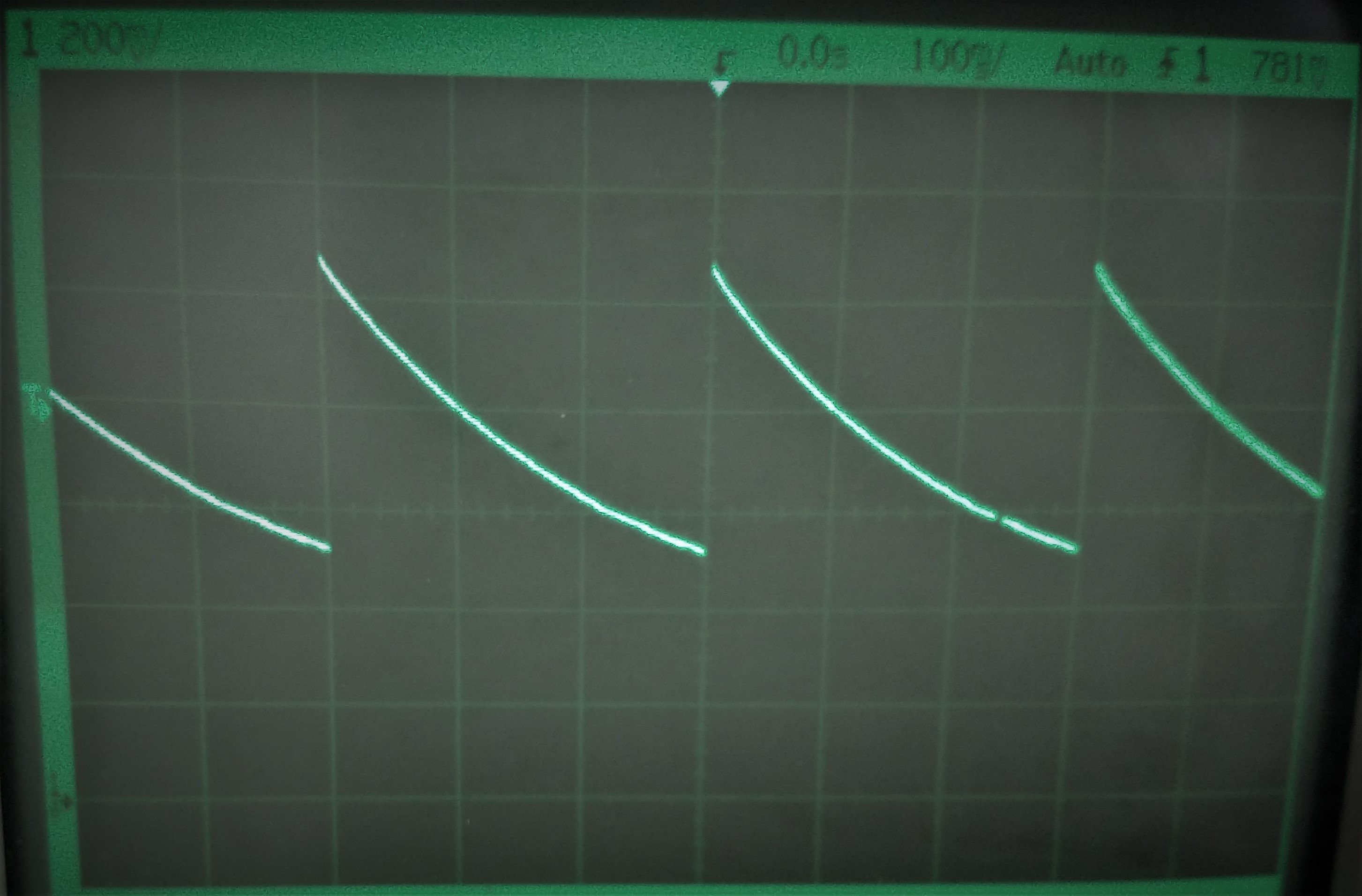
Loaded at 0.5A - oscillating from ~10V -> 5V every 600μs

With the bulk output capacitor inserted (bodged onto the board) the oscillation is still present but the frequency of oscillation is altered (No load - oscillating from ~10V -> ~5V every 800ms)
Design Information
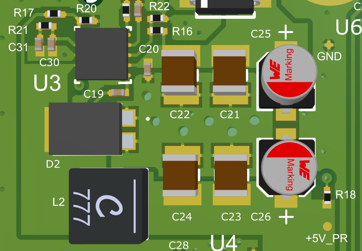
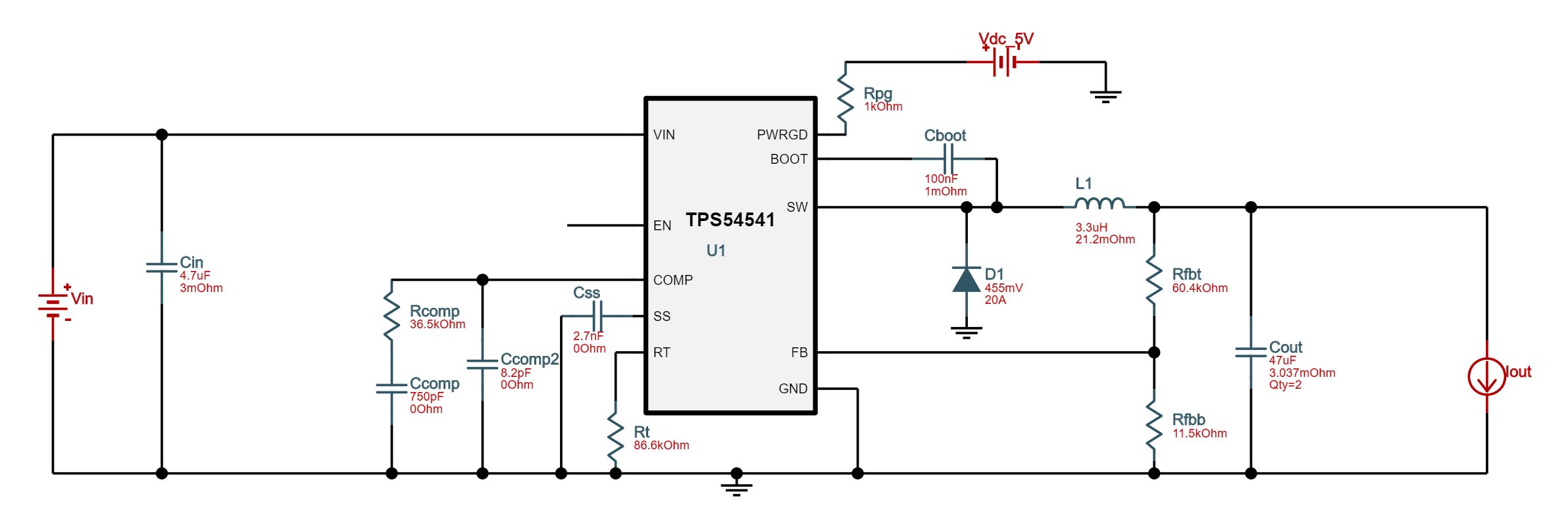
The following is the schematic and layout snippet for the regulator:

I'm guessing it is something compensation related although looking at the recommended design from WEBENCH the compensation scheme is not too dissimilar:
Regarding the layout, I tried to emulate that of the evaluation board.
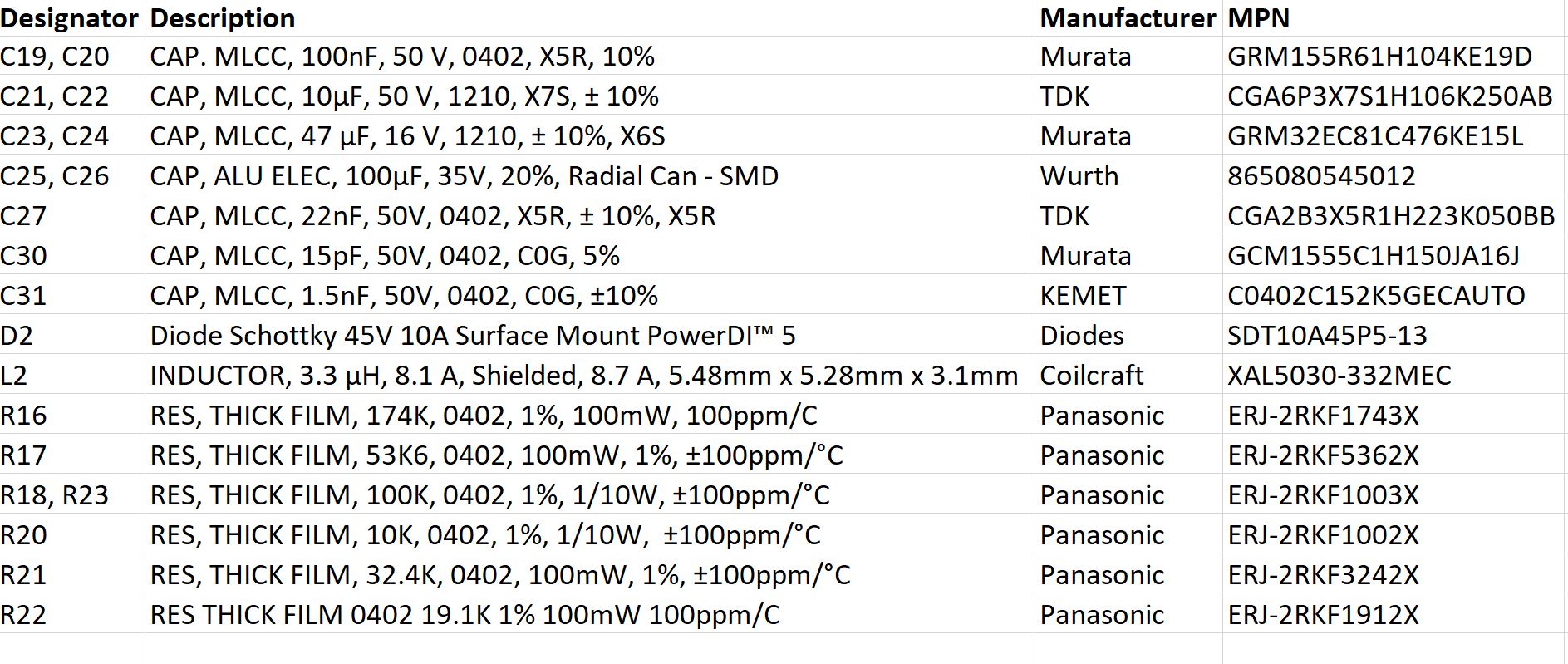
The following is the BOM for the TPS54541