This thread has been locked.

If you have a related question, please click the "
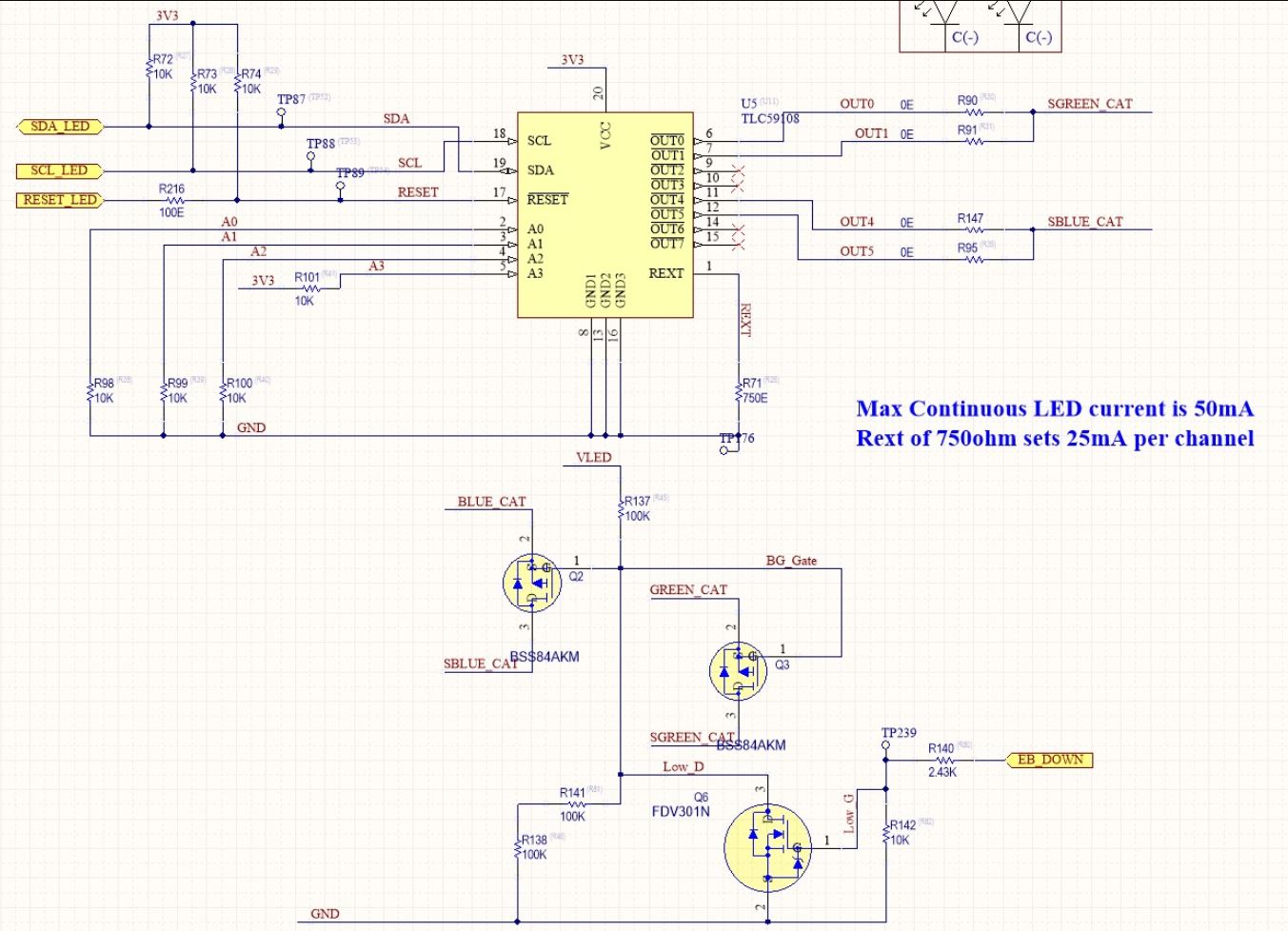
Ask a related question" button in the top right corner. The newly created question will be automatically linked to this question.

TLC59108: Trouble with open circuit detection

Part Number: TLC59108

From my reading of the datasheet it is my understanding that no matter which Iout target is set, the threshold for open circuit detection is always half of the Iout target value. If target is 10mA, threshold is 5mA If target is 40mA, threshold is 20mA My question relates to the circuit image attached. Would, for any reason, the circuit of Q2, Q3, Q6 affect the constant current performance of the TLC59108? In our implementation the LEDs are illuminating, but the open circuit detection is not working correctly. We are normally showing the LEDs in open circuit, when the LEDs are illuminating.

  • Hi

    Is it OK to measure the output current on your board?

  • Hi Hardy,

    The measured current through our LEDs is ~50mA, as per design.

    We have designed for 25mA per channel, and use 2 channels for each of our 2 strings of 3 LEDs.

    Regards,

    Damien

  • Hi Damien,

    So for the situation that you mentioned when open detection did not work normally, how much the output current measured?

    From my side, I think the Q2/Q3 should not impact output current, if BG_Gate set at proper voltage. As for Q6, I think it is used to control BG_Gate right? It should also not influence the outputs.

    One thing I am curious is that TLC59108 can support max to 120mA output current, why you parallel 2 channels for one LED string?

  • Hi Hardy,

    The failure is intermittant. We normally measure a current of ~50mA. In that case the EFLAG register value returned was correct.

    You are right voltage on net BG_Gate is controlled by Q6.

    2 parallel channel outputs, with each channel driving 25mA is the example from the TLC59108 datasheet. Our LED is rated to 50mA, so it matched our requirements.

    Can you tell me, is the attached image an expected waveform? We have a string of 3 LEDs in series per channel. The scope plot was taken at the LEDs.

  • Hi Damien,

    What point is the yellow wave tested, the Anode of LED? And what the register setting of this tested output?

    Green wave showed that output current are constant. I suppose the voltage on LED should also be stable. Can you help to test VLED to see if it is stable?

  • Hi Hardy,

    VLED is stable. It is nominally 15V. When measured on the scope it was ~14.76V

    We have a string of 3 LEDs in series. Their maximum forward voltage drop is 4V. Giving a combined maximum forward voltage drop of 12V. How much voltage overhead do we need to drive each channel to 25mA ?

    We calculate we have a minimum of 2.25 V above the combined maximum forward voltage drop. Is this enough?

    The yellow scope plot is taken at the cathode of the last LED in the string (of 3 LEDs in series) before the input to the TLC59108 at channels OUT0 & OUT1. This is at the net named SGREEN_CAT.

    The register setting is 05h in register 0Ch (both channels are fully ON)

    Thanks

    Damien

  • Hi Damien,

    Sorry for late reply. You could refer Figure 2 in datasheet for the question how much voltage overhead do we need to drive each channel to 25mA. 1V dropped on output pin should be enough to drive 25mA current.

    This triangular wave voltage looks litter confused for me. Output of our device is current sink so that it generate current but not voltage. The triangular wave should be influenced by peripheral circuit. Does Q2 or Q3 have some regular on/off action?

  • Hi Hardy,

    The Gate of Q2 / Q3 is a steady voltage and both Q2 and Q3 are ON as expected.

    Regards,

    Damien

  • Hi Hardy,

    What is the minimum length of time that must be allowed for a read of the EFLAG register after one of the 8 channels has been set to fully ON, in either register 0Ch or 0dh, so that the open circuit detection returns a closed circuit result?

    Thanks,

    Damien

  • Hi Damien,

    Since the effective current value was collected for open detection. It is recommended to wait at least 5 PWM cycles.

  • Hi Hardy,

    We have the driver OUTs set to fully on, not PWM mode.

    Can you tell me what is the minimum time when they are fully ON?

    Thanks,

    Damien

  • Hi Damien,

    The output have rising time due to the parasitic capacitor on board. I think you could measure the rising time and wait at least 10 times of it.

  • Hi Hardy,

    At the end of a read, should the master send an ACK or a NACK?

    We have used device address 90h ( binary 1001 000) . We have only one slave on the bus. Will this cause a problem?

    Does this image look correct for a read?

    Thanks,

    Damien

  • Hi Damien,

    The waveform looks OK, while 10h was read back from 13h register. At the end of read cycle, if master send an ACK, read would continue and register address would auto increment 1. If master send a NACK, read cycle would stop.