This thread has been locked.

If you have a related question, please click the "Ask a related question" button in the top right corner. The newly created question will be automatically linked to this question.

TPS22958: How can I know the leak current of VOUT pin when TPS22958 is disabled

Part Number: TPS22958
Other Parts Discussed in Thread: TS3A24159, , TPS22994

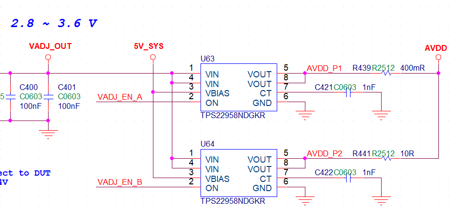
I am designing a DMM, using TPS22958N to switch the current shunt resisters.  I have several questions:

1. when <enable U64 / disable U63 / no load attached> , how much leak current flowing from AVDD_P2-->AVDD-->AVDD_P1-->VOUT(U63) ? 

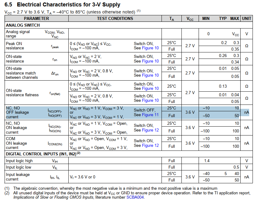
2. TS3A24159 has very little leak current, but don't have enough On-State switch current, Is there any better recommandation?

  • Hi,

    Thanks for your question.

    user4290762 said:

    1. when <enable U64 / disable U63 / no load attached> , how much leak current flowing from AVDD_P2-->AVDD-->AVDD_P1-->VOUT(U63) ? 

    Could you please try to upload your photo again? we can't see it here. Even so, i can kind of guess what might be relevant here and point you to section 7.6 of the datasheet

    When TPS2958 is off, the ISD_VIN spec describes the VIN current when the switch is off, so leakage from VIN thru the switch. 

    If this doesn't help answer your questions please share with us the schematic photo.

    user4290762 said:

    2. TS3A24159 has very little leak current, but don't have enough On-State switch current, Is there any better recommandation?

    I might need some more information to help make a recommendation

    You need an IC to accomplish muxing or DEmuxing? And which current / voltage levels do u need .

    Best

    Dimitri

  • Thank you for your reply~

    1. the leak current I want is in a condition like < Von = 0V  Vout = 0~4V,  Vbias = 5V >, Isd shows the leak current flow into VIN, not Vout, It might not be the parameter I want

    2. I found such parameters in datasheet of TS3A24159  on Page 6, which I attached as below,  But somehow I just can't find it in datasheet of TPS22958. Is that the difference between Analog switch and Load Switch?

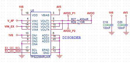
    3. Previously I build a prototype using TPS22994RUKR, It shows around 4uA current with no load, after  I remove the 400mR resister, the current drops to around 0.5uA, so I think it might be the leak current that cause this problem.

    4. I believe  TS3A24159 can work, but I am not satisfied with its 300mA ON-state current and 300mOhm DC resistance,  so I still prefer to use a Load switch,  But Is there any way I can compensate the leak current when measuring uA level current? If the load swtich just can't work on such precise application, is there any better recommendations?

  • Hi,


    user4290762 said:

    1. the leak current I want is in a condition like < Von = 0V  Vout = 0~4V,  Vbias = 5V >, Isd shows the leak current flow into VIN, not Vout, It might not be the parameter I want

    There can be no current leaking INTO VOUT in your case. . Because, you have VIN present, the body diode is reverse biased, the FET DS is at a positive potential. There may neglible current leak /out/ of vout, most due to ISD_VIN. 

    user4290762 said:
    2. I found such parameters in datasheet of TS3A24159  on Page 6, which I attached as below,  But somehow I just can't find it in datasheet of TPS22958. Is that the difference between Analog switch and Load Switch?

    I am not sure why that part has this specced, but i think its because that switched is designed to function bidirectionally. We also have power switches that can function bidirectionally, (efuse for example). Because of the phenomenon i mentioned, we dont . I have done some bench testing, and even in the case where VOUT-VIN is positive, and VON is off. (as long as body diode doesn't become forward biased), there is <<uA range of leakage. 

    user4290762 said:

    3. Previously I build a prototype using TPS22994RUKR, It shows around 4uA current with no load, after  I remove the 400mR resister, the current drops to around 0.5uA, so I think it might be the leak current that cause this problem.

    Also, i dont understand what you mean with the 400mOhm resistor. When you remove it? short to ground, there is less leakage current youre seeing? That doesn't make sense, higher Resistance should necessarily reduce leakage, though at these low current levels i am not sure hwo accurately we could measure the difference. 

    4. I believe  TS3A24159 can work, but I am not satisfied with its 300mA ON-state current and 300mOhm DC resistance,  so I still prefer to use a Load switch,  But Is there any way I can compensate the leak current when measuring uA level current? If the load swtich just can't work on such precise application, is there any better recommendations?

    According to your test condition, your VIN is ~1.8V so you really should be seeing 10s of nA typical. How are you measuring the current?

    We dont have power switch that really youre going to see lower than the #s in teh datasheet, there is a push for lower Ron to increase efficiency, and targetting the lower Ron can lead to slighly increase IDS/ISD leak. If you need something with max 1nA leakage we dont have a device like that. 

     Best

    Dimitri

    1. The bench test you did really helps a lot ! As long as the reverse current is far below uA scale, I will be more confidential with TPS22958.
    2. As to the 3.5uA unknown leak Current, When I measure uA current using TPS22994 ( U5 ), Channel 2 is ON, Channel 1/3/4 are OFF, the V_AP (VIN1/VIN2) is supplied with about 3V, but The VIN_EX (VIN3/VIN4) is Floating, Is that a problem?

  • Hi, 

    sorry, i didn't see the question as the thread was marked resolved. 

    If you want to measure the leakage from just one channel to output, it shouldn't matter if the other channels are completely floating, as i don't think there is a potential to self-power anything like that (reverse conduction is possible)