This thread has been locked.

If you have a related question, please click the "Ask a related question" button in the top right corner. The newly created question will be automatically linked to this question.

LM5175: I hear a sound(noise) from LM5175 circuit

Part Number: LM5175
Other Parts Discussed in Thread: CSD17308Q3, LM5176

I heard the sound on our own designed TDA4 board, and we found that it was actully caused by the LM5175 ciruit.

At the same time,  the TDA4 board can not boot, the UART has no output.

When I measure the input voltage and output voltage of the LM5175 circuit, the LM5175 circuit pull down the 12V input voltage to 5.58V, and output 2.9V.

the LM5175 ciruit schematic is the same as the TDA4 EVM CPB, is designed to output 12V. 

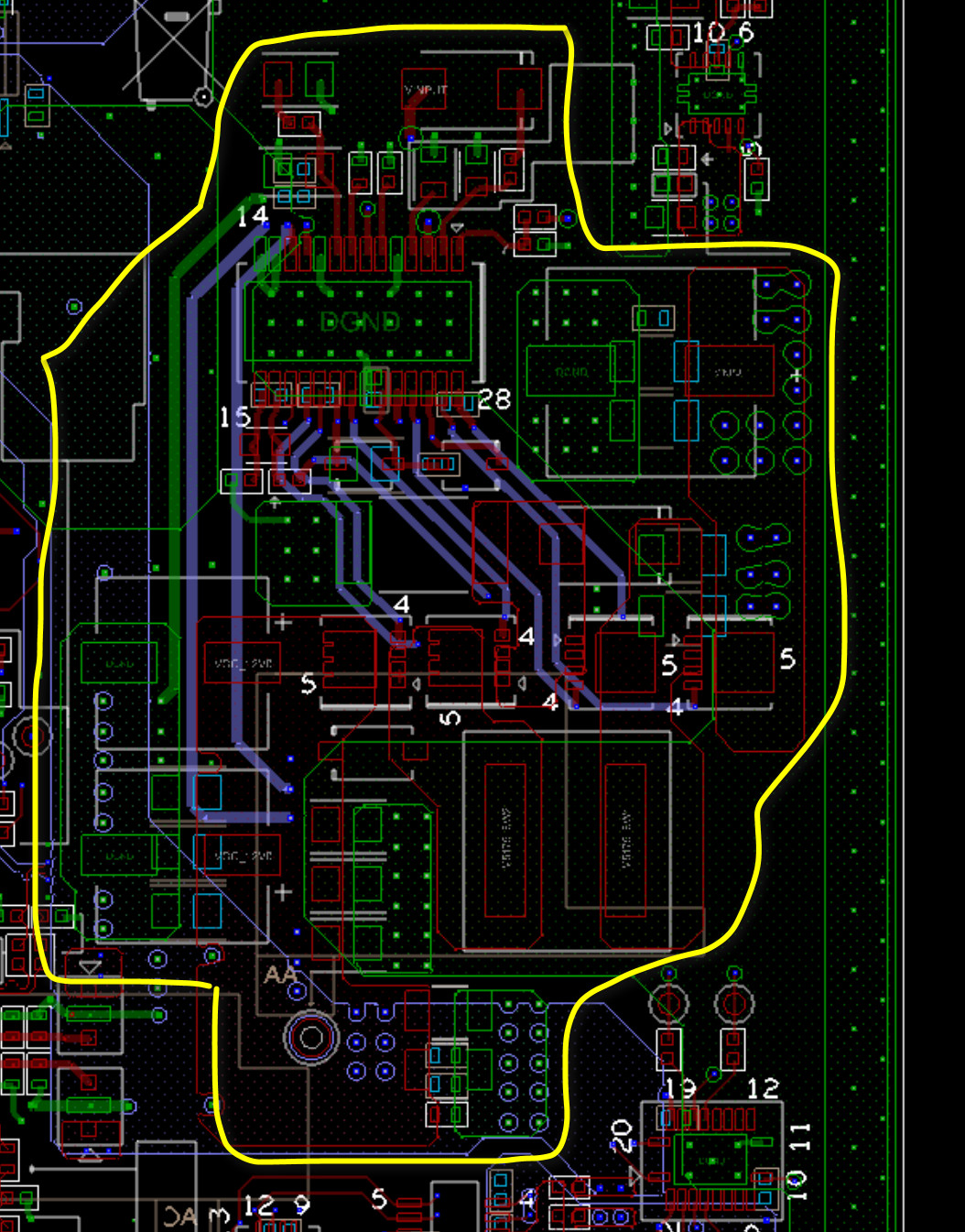
the LM5175 PCB Layout is changed, not the same as the TDA4 EVM CPB. 

when we test our own designed TDA4 board, we use 12V input voltage and we meet this situation, and board does not boot.

when we use 24V input voltage, the board can boot, but I can still hear the sound from LM5175, and LM5175 output 7.5V(not 12V).

Is the LM5175 IC damaged?

Thanks.

  • Hello Hui Liu,

    Which EVM schematic did you take as basis for your circuit? I am confused by the name.

    Would you please measure the input voltage directly at the input capacitor when the converter has started with the higher voltage level? Please measure at the same time the SS pin, the output voltage as well as the SW1 pin.

    Best regards,
    Brigitte

  • HI Brigitte,

    Thanks for your reply.

    Let me add more detail about this issue.

    Customer make 10 sample board. And 6 pcs of 10 have the same problem as following:

    When work a while normally (Vin=12V, Vout =12V), it suddenly has pull down output to 2.58V;

    After that, improve 12Vin to 24Vin, the output is 5.5V, still abnormal because it should be 12V... And CS pin has no output.

    Customer's concern is whether their PCB or SCH is ok Will PCB layout have so big impact on it?

  • Hello Amelie,

    There is nothing inside the IC that would pull the output down. If the converter regulates properly for a while, something is happening that the output is suddenly changing. Please take measurements of the input voltage, the output voltage as well as the switch nodes at the moment when the output falls to get a better understanding of what is happening when the output is suddenly falling.

    Interesting nodes are as well CS, SS, FB and COMP.

    CS pin is an input pin, not an output pin.

    It is possible that the layout causes overheat after some time, but here it is necessary to know the load while the converter is working normal and when the output is pulled lower.

  • Thanks for your reply.

    The LM5175 circuit schematic is from the TDA4 Common Processor Board(CPB),  https://www.ti.com/tool/J721EXCPXEVM, just the EN pin of LM5175 connection is changed from input voltage to 5V in board.

    LM5175 circuit in our own TDA4 board.

    LM5175 circuit in our TDA4 EVM Common Processor Board(CPB).

  • Hello Amelie,

    Thanks for your reply.

    In 10 sample boards, when power on(DC power supply give 12V to the board), 6pcs of 10 make abnormal noise(sound) .

    At the same time, we can see that the board's serial port terminal has no data or data is abnormal. This indicates that TDA4 did not boot, or that TDA4 boot incorrectly. They can not work. These 6 pcs boards can not work when they are made.

    And we found that it was LM5175, which was not working properly and pulled down the input voltage level, causing TDA4 to fail to boot.

    Then we got the VINPUT( power source of all DC-DC include LM5175 in board ) voltage waveform and LM5175 output voltage waveform as below.

    Other 4 pcs board of 10 can boot, and the board's serial port terminal output correct data, but one pcs board is special.

    This special board has been working normally ever since it was manufactured, but it suddenly made an abnormal noise(sound) when it was powered on. After measurement, we found that the input and output voltage is abnormal, similar to the 6pcs of 10 that did not work properly when they were manufactured.

    The VINPUT waveform when LM5175 circuit is abnormal is as follows:

    The LM5175 output waveform when LM5175 circuit is abnormal is as follows:

  • Hello ,

    Thanks for your reply.

    The load current of the LM5175 is very light, almost zero.

    Because the 12V output of LM5175 is used to power the cameras with a rated input voltage of 9-16V, none of the cameras are connected now.

    the pcb layout picture with inner layer route is as follows:

  • Hello Hui Liu,

    Would you please check if adding more input capacitors (several 100uF with low series resistance) can help to reduce the problem?

    Please check in addition if the problem changes when you increase the input voltage.

  • Hello Brigitte,

    Thanks for your reply.

        Today we have repaired the LM5175 circuit of 2 boards. After replacing U247(CSD17308Q3), the output of LM5175 is normal.

        The NMOS's G-S resistor is about 10ohm, G-D resistor is about 10ohm, D-S resistor is about 10 ohm. It was damaged, wasn't it?
        May the NMOS be damaged due to PCB Layout? I also checked the differance between my PCB Layout and TDA4 Common Processor Board, as shown in the figure below.
        The major difference is GND VIA. TDA4 EVM CPB has some  GND VIAs between the traces LM5175_HDRV1,LM5175_SW1,LM5175_LDRV1 and LM5175_HDRV2,LM5175_SW2,LM5175_LDRV2 and CS.
        And TDA4 EVM CPB has more VIAs.
        Does the PCB Layout has so such a big impact? Will it cause NMOS damage?
        In current PCB Layout, will it be better to use LM5176?
        Thanks a lot.
  • Hello Hui Liu,

    In general the PCB layout of any power supply makes or breaks the converter. If the PCB layout is bad, a converter will not work properly, not work at all, get damaged or even get on fire. So yes, the PCB layout has a great influence on the operation of any converter. This is not specific to LM5175.

    I am sorry, but with the layout picture above, I am not able to check if the layout is good or has some issues.

    For the transistor damage, please check the following points in detail: SW1 and SW2 ringing. It is possible that noise during the switching operation causes undershoots and or overshoots that damage the switch or the controller.

    Another possible problem could be the temperature of the transistor. It is possible that it gets too hot.